


52C,P
SERIES
16
■
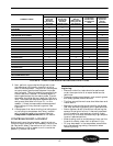
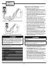
TOOLS NEEDED
— The following list includes the
recommended tools and devices for removing and
replacing the compressor.
■
REMOVING THE COMPRESSOR
— Follow the
steps below to remove the compressor:
1. Disconnect all power to unit.
2. Remove unit from wall sleeve as detailed in the
UNIT DISASSEMBLY section. The unit weighs
up to 150 pounds. Seek assistance or use a lifting
device when removing unit from wall sleeve.
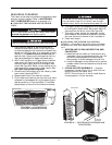
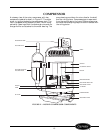
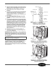
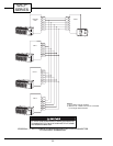
3. If the unit is a heat pump: Disconnect the wire
plug on the reversing valve solenoid and carefully
remove the outdoor thermostat capillary from the
outdoor coil. See Figure 32.
4. Attach the piercing valve to the suction side pro-
cess tube below the crimps. Attach Carrier
TOTALTEST® kit (Part No. TT1-001), to the
piercing valve to verify acidity of the system. After
verifying the system acidity, remove the refriger-
ant using a certified refrigerant recovery system.
5. When all the refrigerant has been recovered,
remove the terminal cover from the compressor
with a nut driver. Disconnect the 3 wires from the
compressor and label the location of each. Once
the wires are labeled, replace the terminal cover
to protect the compressor terminals.
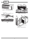
6. Remove the air system components by following
the procedure detailed in the ACCESSING UNIT
COMPONENTS section.
7. Remove the piercing valve and cut the crimped
portion of both process tubes off with a small tub-
ing cutter. Braze an access valve on each process
tube. Using a torch, disconnect the suction and
discharge tubes from the compressor connections.
8. Remove the compressor mounting bolts, and
remove the compressor.
9. For all units: Remove and replace the strainer
and capillary tubes from the system. See Figure 32
for strainer and capillary tube location.
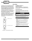
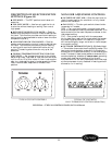
10. For Heat/Cool Units: Use an in-line filter drier
(P/N P504-80845). The filter drier can be installed
in any location in suction line. See Figure 33A for
general installation location.
For Heat Pump Units: Use an in-line filter drier
(P/N P504-80845) and install between the
reversing valve and the compressor accumu-
lator. There are several suction tube configura-
tions and the in-line filter drier will be field piped
and brazed into the suction tube for your unit. See
Figure 33B for a general installation location.
11. Remove the grommets from the existing compres-
sor and install them onto the new compressor.
For compressors that are known to be dam-
aged: Remove refrigerant prior to disconnecting
compressor wires. Damaged hermetic compressor
terminals may become loose and eject from the com-
pressor. Wear safety glasses and keep your face
away from the area above the terminals when
removing compressor wires.
1
/
2
-in. and
3
/
8
-in. Tube Benders
1
/
2
-in. Nut Driver
5
/
16
-in. Nut Driver
Flat Head Screwdriver
Piercing Valve
2 Parker Access Valves (Part No. AVUSE-5)
Pinch Off Tool
Filter Drier — All Units (Part No. P504-80845)
Carrier TOTALTEST Kit (Part No. TT1-001)
Totalclaim System
Charging Cylinder or an Electronic Scale
Refrigerant-22
Tubing Cutter
Torch
Nitrogen Cylinder with Regulator
Strainers
Capillary Tubes
The compressor may still be hot from the brazing
process.
IMPORTANT: Any time the compressor is
replaced, the strainer and capillary tubes must
be removed and replaced also.
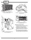
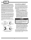
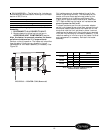
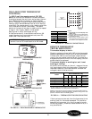
FIGURE 30 — SHORTED/OPEN WINDINGS TEST
FIGURE 31 — GROUNDED WINDINGS TEST