


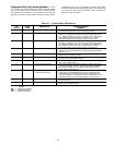


Diagnostic LEDs (Light-Emitting Diodes) — There
are 3 LEDs (red, yellow, and green) on the lower right hand
side of the control board. The red light is used to check
unit operation and alarms. A constant pulse is normal unit
operation. A series of quick blinks indicates an alarm. Refer
to Table 20 below for a description of alarms. The yellow
LED blinks during transmission with the CCN (Carrier Com-
fort Network). The green LED blinks during transmission
with the expansion board.
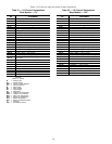
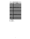
Table 20 — Control Board LED Alarms
LED
BLINKS
ERROR
CODE
DESCRIPTION
TROUBLESHOOTING
COMMENTS
1 Normal Operation The expansion board and control board flash the red LED in one-
second intervals when the board is operating properly.
2 HF-13 Compressor 1 Safety The high or low pressure safety switch for compressor no. 1 has
opened for 3 seconds. The error will be cleared and compressor
no. 1 will be allowed to turn on in 15 minutes. If the safeties have
been tripped 3 times in 90 minutes, compressor no. 1 will be
locked out until the control board has been manually reset.
3 HF-14 Compressor 2 Safety The high or low pressure safety switch for compressor no. 2 has
opened for 3 seconds. The error will be cleared and compressor
no. 2 will be allowed to turn on in 15 minutes. If the safeties have
been tripped 3 times in 90 minutes, compressor no. 2 will be
locked out until the control board has been manually reset.
4 HF-15 Thermostat Failure The thermostat is calling for both heating and cooling at the
same time. The unit will operate on a first call basis and will auto-
matically reset.
5 HF-05 SAT Thermistor Failure The supply-air temperature (SAT) sensor has failed. First check for
wiring errors, then replace sensor.
6 HF-06 OAT Thermistor Failure The outside-air temperature (OAT) sensor has failed. First check
for wiring errors, then replace sensor.
7 HF-03 Space Temp. Sen. Failure The space temperature sensor has failed. First check for wiring
errors, then replace sensor.
8 HF-12 RAT Thermistor Failure The return-air temperature (RAT) sensor has failed. Ensure that
the unit is a VAV unit. If NOT a VAV unit set DIP switch position 1
to the closed position and reset power. Then check for wiring
errors. Finally, replace sensor.
9 SE-05 Loss of Communications
with Expansion board
Communications between the expansion board and the control
board have been interrupted. Ensure that an expansion board
is installed and wired using the wire harness supplied with the
expansion module. If an expansion board is not used ensure that
DIP switch position 3 is in the closed position, and reset power.
10 HF-16 Control Board Failure Generated when hardware has failed on control board. Replace
the control board.
11 HF-17 Expansion Board Failure Generated when hardware has failed on the expansion board.
Replace the expansion board.
LEGEND
DIP — Dual In-Line Package
LED — Light-Emitting Diode
VAV — Variable Air Volume
49