


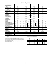
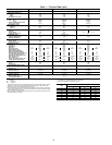
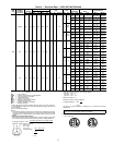
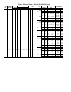

Table 2 — Evaporator Fan Motor Data
UNIT
SIZE
MOTOR
HP
MOTOR
SHAFT
DIAMETER
(in.)
FAN
SHAFT
SPEED
(rpm)
MOTOR
SHEAVE
MOTOR
SHEAVE
PITCH
DIAMETER
(in.)
BUSHING
DIAMETER
(in.)
FAN
SHEAVE
FAN
SHEAVE
PITCH
DIAMETER
(in.)
BUSHING
DIAMETER
(in.)
BELT
OUTSIDE
BELT
LENGTH
BELT
TENSION
(Lb @
.24 in.)
024
5 1.12 725 BK52 4.6 None-1.125 1B5V110 11.1 B-1.6875 BX59 62 5.02
10 1.38 924 BK72 6.6 None-1.375 1B5V124 12.5 B-1.6875 BX60 63 7.05
15 1.62 1088 1B5V68 6.9 B-1.625 1B5V110 11.1 B-1.6875 5VX590 59 9.38
028
7.5 1.38 773 BK55H 4.9 H-1.375 1B5V110 11.1 B-1.6875 BX56 59 6.87
10 1.38 962 BK67H 6.1 H-1.375 1B5V110 11.1 B-1.6875 BX56 59 7.26
15 1.62 1119 1B5V70 7.1 B-1.625 1B5V110 11.1 B-1.6875 5VX590 59 9.17
030
10 1.38 843 BK72 6.6 None-1.375 1B5V136 13.7 B-1.6875 BX62 65 6.96
15 1.62 1056 1B5V66 6.7 B-1.625 1B5V110 11.1 B-1.6875 5VX590 59 9.60
20 1.62 1182 1B5V74 7.5 B-1.625 1B5V110 11.1 B-1.6875 5VX600 60 11.67
034
10 1.38 896 BK70H 6.4 H-1.375 1B5V124 12.5 B-1.6875 BX60 63 7.20
15 1.62 1088 1B5V68 6.9 B-1.625 1B5V110 11.1 B-1.6875 5VX590 59 9.38
20 1.62 1182 1B5V74 7.5 B-1.625 1B5V110 11.1 B-1.6875 5VX600 60 11.17
038
10 1.38 788 2BK47 4.1 None-1.375 2B5V90 9.1 B-1.6875 BX51 54 5.49
15 1.62 966 1B5V68 6.9 B-1.625 1B5V124 12.5 B-1.6875 5VX630 63 9.22
20 1.62 1050 1B5V74 7.5 B-1.625 1B5V124 12.5 B-1.6875 5VX650 65 10.02
044
15 1.62 966 1B5V68 6.9 B-1.625 1B5V124 12.5 B-1.6875 5VX630 63 9.54
20 1.62 1035 1B5V80 8.1 B-1.625 1B5V136 13.7 B-1.6875 5VX670 67 10.37
25 1.88 1162 1B5V90 9.1 B-1.875 1B5V136 13.7 B-1.6875 5VX680 68 10.88
048
20 1.62 1019 2B5V52 5.3 B-1.625 2B5V90 9.1 B-1.6875 5VX550 55 7.93
25 1.88 1135 2B5V58 5.9 B-1.875 2B5V90 9.1 B-1.6875 5VX560 56 8.66
30 1.88 1182 2B5V76 7.5 B-1.875 2B5V110 11.1 B-1.6875 5VX610 59 9.07
NOTE: Motor shaft speed is 1750 rpm. The fan shaft diameter is 1
11
⁄
16
inches.
ROOF MOUNT — Check building codes for weight distri-
bution requirements.
Step 3 — Field Fabricate Ductwork — Secure all
ducts to building structure. Use flexible duct connectors be-
tween unit and ducts as required. Insulate and weatherproof
all external ductwork, joints, and roof openings with counter
flashing and mastic in accordance with applicable codes.
Ducts passing through an unconditioned space must be
insulated and covered with a vapor barrier.
To attach ductwork to roof curb, insert ductwork approxi-
mately 10 to 11 in. up into the curb. Connect ductwork to
14-gage roof curb material using sheet metal screw driven
from inside the duct.
The units with electric heat require a 1-in. clearance for
the first 24 in. of ductwork.
NOTE: A 90-degree elbow must be provided in the duct-
work to comply with UL (Underwriters’ Laboratories) codes
for use with electric heat.
Outlet grilles must not lie directly below unit discharge.
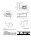
Step 4 — Make Unit Duct Connections
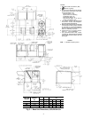
50EJ,EK UNITS — Unit is shipped for through-the-bottom
duct connections. Ductwork openings are shown in Fig. 3
and 4. Attach all ductwork to roof curb. Air distribution
is shown in Fig. 8. Refer to installation instructions shipped
with accessory roof curb for more information.
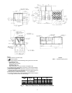
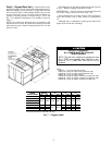
50EW,EY UNITS — Remove shipping covers from supply
and return air openings. Attach field-supplied ductwork to
unit. Use a single duct over both return openings and a single
duct over both supply openings. See Fig. 5 and 6 for duct
opening dimensions. Secure all ducts to the building struc-
ture. See Fig. 9. Use flexible duct connectors between unit
and ducts as required.
Install accessory barometric relief or power exhaust in the
field-fabricated return ductwork. Refer to Position Power
Exhaust/Barometric Relief Damper Hood Section on
page 29 for more information.
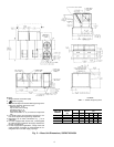
Step5—TrapCondensate Drain — See Fig. 3-6
and 10 for drain location. Condensate drain is open to the
atmosphere and must be trapped. Install a trapped drain at
the drain location. One 1-in. FPT coupling is provided in-
side unit evaporator section for condensate drain connec-
tion. A trap at least 4-in. deep must be used. Trap must be
installed to prevent freeze-up.
Condensate pans are sloped so that water will completely
drain from the condensate pan to comply with indoor air qual-
ity guidelines.
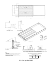
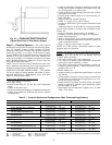
Fig. 8 — Air Distribution — Thru-the-Bottom
Fig. 9 — Air Distribution — Thru-the-Side
11