


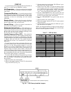

DIP switch configurations for Version 1.0 of the Unit Con-
trol Software are as follows:
• DIP switch 1 configures the unit to operate as a variable
air volume (VAV) or constant volume (CV) unit
• DIP switch 2 configures what type of sensors or thermo-
stats are used with the unit
• DIP switch 3 configures the DDC for use with the elec-
tronic expansion board
• DIP switch 4 is used to field test the unit
• DIP switch 5 configures the unit to use constant volume or
modulated power exhaust
• DIP switch 6 configures the Time Guard override and the
minimum damper position
• DIP switch 7 configures the unit for gas heat or electric
heat
• DIP switch 8 is used to factory test the unit
The DIP switch configurations for Version 2.0 of the unit
control software are as follows:
• DIP switch 1 configures the unit to operate as a VAV or
CV unit
• DIP switch 2 configures the unit to use a space sensor (VAV
units) or a thermostat (CV units)
• DIP switch 3 configures the DDC for use with an elec-
tronic expansion board
• DIP switch 4 is used to field test the unit
• DIP switch 5 is used to enable occupied heating (VAV units)
or specify the type of power exhaust (CV units)
• DIP switch 6 configures the Time Guard override and, when
used with the field test function, sets the minimum damper
position
• DIP switch 7 configures the unit for gas heat or electric
heat
• DIP switch 8 configures the unit for heat pump or air con-
ditioner operation
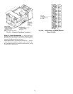
Crankcase Heater(s) — Heater(s) is energized as long
as there is power to the unit, except when the compressors
are operating.
IMPORTANT: Unit power must be on for 24 hours
prior to start-up. Otherwise, damage to compressor may
result.
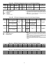
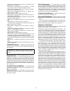
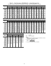
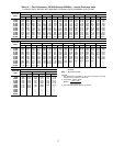
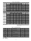
Evaporator Fan — Fan belt and fixed pulleys are factory-
installed. See Tables 12-14 for Fan Performance Data. See
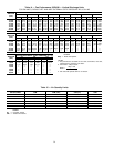
Table 15 for Air Quantity Limits. See Table 16 for Motor
Limitation data. Be sure that fans rotate in the proper di-
rection. Static pressure drop for power exhaust, barometric
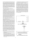
relief damper, and electric heat is negligible. To alter fan per-
formance, see Evaporator Fan Performance Adjustment sec-
tion on page 43.
Condenser Fans and Motors — Fans and motors
are factory set. Refer to Condenser-Fan Adjustment section
(page 44) as required.
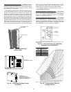
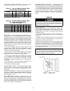
Return-Air Filters — Check that correct filters are in-
stalled in filter tracks. See Table 1. Do not operate unit with-
out return-air filters.
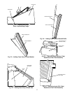
Filter Replacement — To replace filters, open filter
access door (marked with label). Remove inner access panel.
Remove plastic filter retainer in between filter tracks by slid-
ing and pulling outward. Remove first filter by sliding it out
of the opening in filter track. Locate filter removal tool, which
is shipped next to the return air dampers. Use the filter re-
moval tool to remove the remaining filters.
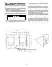
Outdoor-Air Inlet Screens — Outdoor-air inlet screens
must be in place before operating unit.
Economizer Adjustment — Remove filter access panel.
Check that outdoor-air damper is closed and return-air damper
is open.
Economizer operation and adjustment is described in Se-
quence of Operation and Make Outdoor Air Inlet Adjust-
ments sections (this page and page 25), respectively.
Sequence of Operation
NOTE: Unit is shipped with default values that can be changed
through Service Tool or CCN software.
COOLING, CONSTANT VOLUME (CV) UNITS — On
power up, the control module will activate the initialization
software. The initialization software reads DIP switch no. 1
position to determine CV or VAV operation. Next, DIP switch
no. 2 is read to determine if the control is TSTAT or sensor
type operation. The initialization sequence: clears all alarms
and alerts; re-maps the input/output database for CV opera-
tion; sets maximum heat stages to 2; and sets maximum cool
stages to 3. The control module reads DIP switch no. 3 and
determines if the unit will use expansion mode operation.
The TSTAT function performs a thermostat based control
by monitoring Y1, Y2, W1, W2 and G inputs. These func-
tions control stages: cool1, cool2, heat1, heat2, and the in-
door fan respectively. If the TSTAT function is not selected,
the control module determines the occupancy state based on
the system time schedules or with remote occupied/unoccupied
input. If Temperature Compensated Start is active, the unit
will be controlled as in the Occupied mode. User defined set
points are shown in Table 17.
Occupied or unoccupied comfort set points must be se-
lected. Use of the space temperature offset input can also be
configured. The control module will set appropriate operat-
ing mode and fan control. The control module will turn on
indoor fan if in Occupied mode or if the unit is in Unoccu-
pied mode and the space temperature is outside of the un-
occupied comfort set points (Unoccupied Heat or Unoccu-
pied Cool). The control module will then monitor space
temperature against comfort set points and control heating
or cooling stages as required. If the system is in the Occu-
pied mode, the economizer will operate as required. If the
system is in Unoccupied mode, the system will perform night
time free cool and IAQ (indoor air quality) pre-occupancy
purge as required (when functions are enabled via software).
Whenever the DX (direct expansion) cooling is requested,
the outdoor fan will operate.
35