


A3
1
⁄
2
-in. NPT coupling for field power wiring and a
3
⁄
4
-in. NPT coupling for 24-v control wiring are provided in
basepan. In the side post, there are two 2
1
⁄
2
-in. (024-034) or
3-in. (038-048) knockouts for the field power wiring. See
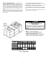
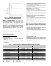
Fig. 3-6. If control wiring is to be brought in through the
side of unit, a
7
⁄
8
-in. diameter hole is provided in the con-
denser side post next to the control box.
If disconnect box is mounted to corner post, be careful
not to drill any screws into the condenser coil.
Routing Through Bottom of Unit — If wiring is brought in
through bottom of unit, use field-supplied watertight conduit
to run power wiring from basepan out through bottom
3
1
⁄
2
-in. hole to the disconnect box and back into unit to the
main control box.
Use strain relief going into control box through 2
1
⁄
2
-in.
diameter hole provided. After wires are in unit control box,
connect to power terminal block (see Power Wiring section
on this page 15).
Low-voltage wiring must be run in watertight conduit from
the basepan to control box and through
7
⁄
8
-in. diameter hole
provided in bottom of unit control box. Field-supplied strain
relief must be used going into the box. After wiring is in
control box, make connections to proper terminals on ter-
minal blocks (see Field Control Wiring section on this page).
Install conduit connector in unit basepan or side panel open-
ings provided. Route power and ground lines through con-
nector to connections in unit control box as shown on unit
wiring diagram and Fig. 13.
Routing Through Side of Unit — Route power wiring in
field-supplied watertight conduit into unit through 2
1
⁄
2
-or
3-in. hole. Strain relief (field supplied) must be used in hole.
See Fig. 13.
Use field-supplied strain relief going into control box through
2
1
⁄
2
- or 3-in. diameter hole provided. After wires are in unit
control box, connect to power terminal block (see Power Wir-
ing section on page 15).
Bring low-voltage control wiring through factory-drilled
7
⁄
8
-in. diameter hole in condenser side post. Use strain relief
going into
7
⁄
8
-in. diameter hole in bottom of unit control box.
After wiring is in control box, make connection to proper
terminals on terminal blocks (see Field Control Wiring sec-
tion on this page).
IMPORTANT: THE VAV (variable air volume) units
incorporate VFD (variable frequency drives) which gen-
erate, use, and can radiate radio frequency energy. If
units are not installed and used in accordance with these
instructions, they may cause radio interference. They
have been tested and found to comply with limits of a
Class A computing device as defined by FCC (Federal
Communications Commission) regulations, Subpart J
of Part 15, which are designed to provide reasonable
protection against such interference when operated in
a commercial environment.
The unit must be electrically grounded in accordance
with local codes and NEC ANSI/NFPA 70 (National Fire
Protection Association).
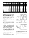
Operating voltage to compressor must be within voltage
range indicated on unit nameplate. On 3-phase units, volt-
ages between phases must be balanced within 2% and the
current must be balanced within 10%.
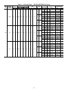
Use the formula in Table 4 to determine the percentage of
voltage imbalance.
IMPORTANT: If the supply voltage phase imbalance
is more than 2%, contact your local electric utility com-
pany immediately.
Unit failure as a result of operation on improper line volt-
age or excessive phase imbalance constitutes abuse and may
cause damage to electrical components.
On 208/230-v units, transformer no. 1 is wired for 230-v.
If 208/230-v unit is to be run with 208-v power supply, the
transformer must be rewired as follows:
1. Remove cap from red (208-v) wire.
2. Remove cap from spliced orange (230-v) wire. Discon-
nect orange wire from black unit power wire.
3. Cap orange wire.
4. Splice red wire and black unit power wire. Cap wires.
IMPORTANT: Be certain unused wires are capped.
Failure to do so may damage the transformers.
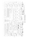
FIELD CONTROL WIRING — Install either a Carrier-
approved accessory thermostat or a CCN (Carrier Comfort
Network) compatible temperature sensor. Thermostats are used
on CV (constant volume) units only. Control box diagrams
are shown in Fig. 14 and 15.
Thermostat Wiring (CV Only) — Install a Carrier-approved
accessory thermostat assembly (per current price pages) ac-
cording to the installation instructions included with the ac-
cessory or these instructions. Locate thermostat assembly on
a solid wall in the conditioned space to sense average
temperature.
Route thermostat cable or equivalent single leads of col-
ored wire from subbase terminals to low-voltage connec-
tions as shown on unit label wiring diagram and in Fig. 16.
NOTE: For wire runs up to 50 ft, use no. 18 AWG (Ameri-
can Wire Gage) insulated wire (35 C minimum). For 50 to
75 ft, use no. 16 AWG insulated wire (35 C minimum). For
over 75 ft, use no. 14 AWG insulated wire (35 C minimum).
All wire larger than no. 18 AWG cannot be directly con-
nected to the thermostat and will require a junction box and
splice at the thermostat.
Set heat anticipators settings to 0.1 for all voltages. Set-
tings may be changed slightly to provide a greater degree of
comfort for a particular installation.
Sensor Wiring (CV or VAV) — The temperature sensor is
wired into the unit control board. See Fig. 17.
The unit is controlled with a T55, T56 (CV only), or T57
zone sensor. Terminal TH on the sensor is connected to T1
of the base module board. Terminal COM on the sensor is
connected to T2 on the base module board. If a T56 set point
override sensor is used, the override connection SW on the
sensor is connected to T3 on the base module board.
VAV units using Version 1.0 of the unit control software
may operate without a space temperature sensor during oc-
cupied schedules, but unit will not provide unoccupied heat-
ing or cooling.
VAV Units — VAV units require a field-supplied heat inter-
lock relay (HIR) to drive the air terminal wide open when in
heat mode. The HIR part number is HN61KK041.
Remote Field Control (Units Running Version 1.0 of Unit
Control Software) — A switch closure across terminals R
and Y1 on TB-3 will initiate the Occupied mode. This can
be done manually as well as through a field-supplied
timeclock.
16