


Power Exhaust — The optional non-modulating power
exhaust (CV only) is a two-stage design where the operation
of the exhaust fans is linked to economizer position. When
the supply fan is running and the economizer is 25% open,
the base module closes contacts, activating 2 exhaust fans.
When the economizer position reaches 75% open, the base
module activates the other 2 exhaust fans. The fans will turn
off when the economizer closes below the same points. The
economizer position set points that trigger the exhaust fans
can be modified, but only through use of the Service Tool,
Comfort Works, or Building Supervisor Software. If single-
stage operation is desired, adjust the economizer set points
to identical values at the desired point to activate all exhaust
fans.
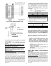
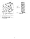
The optional modulating power exhaust (VAV standard,
CV optional) is controlled by a modular electronic se-
quencer system. This system consists of a model R353 sig-
nal input module and 4 model S353 staging modules. The
signal input module receivesa0to10vdcsignal from the
building pressure transducer, which is mounted adjacent to
the supply static transducer behind the filter access panel.
The modules are mounted just below the unit control board.
The left module is the R353, and the 4 modules on the right
are S353 modules for stages 1 through 4. On the unit wiring
label, the R353 is designated PESC, and the S353 modules
are designated PES1 through PES4.
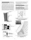
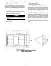
The building pressure transducer range is −0.5 to
+0.5 in. wg. It is powered bya0to10vdcsignal. A factory-
installed hose at the ‘‘Lo’’ connection leads to atmosphere,
and a field-supplied hose must be connected to the ‘‘Hi’’con-
nection and led into the building to a point where building
pressure is to be controlled. There is a plug button in the
bulkhead just above the transducers, for use in leading the
hoses into the building via the return air ductwork.
There are 3 adjustments at the R353 module, all of which
have been factory set. In the center of the circuit board is a
set of 4 pins with a jumper, labeled J2. This determines the
mode of operation. The bottom 2 pins must be jumpered for
direct operation. Direct operation means that the staging mod-
ules are activated in sequence as the input signal
increases.
At the upper right corner of the board is a set of 5 pins and
jumper, which determines the time constant for the control.
The time constant is the delay in response built into the con-
trols. The jumper should be on the middle or bottom 2 pins,
for the maximum time constant. The delay can be decreased,
if desired, by moving the jumper progressively upward, al-
ways jumpering adjacent pins.
At the lower left corner of the board below the terminal
strip is a resistor marked R27. This must be removed in or-
der to obtain the 0 to 10 vdc signal output. There will not be
a resistor on a factory-supplied module, but a resistor may
be present on a replacement module and must be removed.
The R353 module has a terminal block with 7 connec-
tions available for wiring. The 2 right-hand terminals are for
the 24 vac and common connections. The next 2 terminals
are for the 0 to 10 vdc signal. Consult the wiring label for
wire identification if replacing the module. The 3 left-hand
terminals are not used for this application.
The S353 module has an LED (light-emitting diode), a set
of 4 jumper pins, and 2 potentiometers. The LED will light
whenever the module is activated, providing a visual indi-
cation of the number of exhaust fans running. The jumper
pins are arranged in a square format. Two jumpers are used
to determine the mode of operation (direct or reverse). The
2 jumpers must be arranged horizontally for direct action
(factory set).
At the top of the module are 2 potentiometers. The left
potentiometer adjusts the offset. The right potentiometer ad-
justs differential. The potentiometers are factory set for a
nominal 0 in. wg building pressure.
The offset set point is defined as the point at which a mod-
ule turns off a fan, and is measured in terms of percent of the
input signal. For control purposes, 0 offset is at an arbitrary
‘‘floor’’ which is established at 10% of the input signal, or
1 vdc. In this example, the first stage will turn off at 30%
(3 vdc), and the offset potentiometer will be set at 20%. The
second stage will turn off at 50% signal (5 vdc), and the off-
set potentiometer will be set at 40%. The fourth stage is at
the maximum 75% offset, which equates to 85% signal or
8.5 vdc. The offset potentiometer is calibrated in 10%
increments.
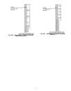
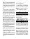
Table 8 relates building pressure to signal level.
Table 8 — Potentiometer Signal Levels
BUILDING PRESSURE
(in. wg)
SIGNAL LEVEL
(vdc)
−0.50 2
−0.25 4
0.00 6
0.25 8
0.50 10
If the building pressure is controlled at 0 in. wg, offset of
the first stage should be set at 50%, which equates to 60%
of the input signal, or 6 vdc. The other stages can then be set
as desired between 50% and 75%.
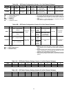
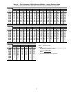
The default offset set points for modulating power ex-
haust are shown in Table 9.
Table 9 — Power Exhaust Default Set Points
STAGE OFFSET
DIFFE-
RENTIAL
OFF
VOLTAGE
ON
VOLTAGE
OFF
STATIC
PRESSURE
(in. wg)
1 50% 3% 6.0 6.3 0.00
2 55% 3% 6.5 6.8 0.06
3 60% 3% 7.0 7.3 0.12
4 64% 3% 7.4 7.7 0.18
The differential set point is the difference between the
turn off point and the turn on point for each module. It also
is calibrated in terms of percent of input signal, and has a
range of 1% to 7%. The differential potentiometer is cali-
brated in 1% increments, and is factory set at approximately
3%. It is recommended to leave the set point at 3%, to mini-
mize cycling of the fans.
The offset and differential potentioments have been fac-
tory set for atmosphereic pressure. Do not change these set-
tings until there is some experience with the building. In most
cases the factory settings will be satisfactory. However, if
the building pressure is not being maintained as desired, then
some minor adjusting on a trial and error basis can be made.
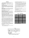
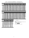
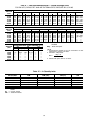
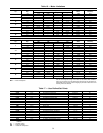
Direct Digital Controls DIP Switch Configura-
tion —
The Direct Digital Control (DDC) board must be
configured for each application. The DDC board is config-
ured through the DIP switches located on the board. There
are 8 DIP switches which configure 8 different applications
of the DDC. See Tables 10A and 10B. DIP switch 1 is on the
left of the block. DIP switch 8 is on the right of the block.
To open a DIP switch, push the switch up with suitable tool
(small-blade screwdriver). To close a DIP switch, push the
switch down. Factory settings are shown in Tables 11A
and 11B.
33