


The control module will operate economizer, run diag-
nostics to monitor alarms/alerts at all times, and respond to
CCN communications to perform any configured network
POC (product outboard control) functions such as time/
outdoor-air temperature broadcast and global occupancy broad-
cast. When the optional expansion I/O board is employed, it
will: perform a periodic scan and maintain a database of ex-
panded I/O points; perform Fire/Smoke control (power ex-
haust required); if in Occupied mode, perform IAQ control
and monitor the fan, filter, demand limit, and field-applied
status (with accessories).
If thermostats are used to energize the G input, the control
module will turn on the indoor fan without delay and open
the economizer dampers to minimum position. If thermo-
stats are used to deenergize the G input, the control module
will turn off the indoor fan without delay and close the econo-
mizer dampers.
When cooling, G must be energized before cooling can
operate. The control module determines if outdoor condi-
tions are suitable for economizer cooling using the standard
outdoor air thermistor. For the economizer to function for
outside air cooling: the enthalpy must be below the enthalpy
set point; the outdoor-air temperature must be equal to or
less than the High Outdoor Air Temperature Lockout (de-
fault is 65 F); the SAT (supply-air temperature) thermistor
must not be in alarm; and the outdoor air reading is avail-
able. When these conditions are satisfied, the control mod-
ule will use economizer as the first stage of cooling.
When Y1 input is energized, the economizer will be modu-
lated to maintain SAT at the defined set point. (The default
is 55 F.) When SAT is above the set point, the economizer
will be 100% open. When SAT is below the set point, the
economizer will modulate between minimum and 100% open
position. When Y2 is energized, the control module will turn
on compressor 1 and continue to modulate the economizer
as described above. If the Y2 remains energized and the SAT
reading remains above the set point for 15 minutes, com-
pressor 2 will turn on. If Y2 is deenergized at any time, only
the last stage of compression that was energized will be turned
off. If outdoor conditions are not suitable for economizer cool-
ing, the economizer will go to minimum position and cycle
compressors 1 and 2 based on demand from Y1 and Y2 re-
spectively. The compressors will be locked out when the SAT
temperature is too low (less than 40 F for compressor 1 and
less than 45 F for compressor 2).After a compressor is locked
out, it can restart after normal time-guard period.
The Time Guard function maintains a minimum off time
of 5 minutes, a minimum on time of 10 seconds, and a
minimum delay before starting the second compressor of
10 seconds.
When heating, the heat stages respond to the demand from
W1 and W2 of the thermostat input. Heating and cooling
will be mutually locked-out on demand on a first call basis.
The heating and the cooling functions cannot operate
simultaneously.
COOLING, VARIABLE VOLUME UNITS — On power up,
the control module will activate the initialization software.
The initialization software reads DIP switch no. 1 position
to determine CV or VAV operation. The initialization se-
quence: clears all alarms and alerts; re-maps the input/
output database for VAV operation; sets maximum heat stages
to 1; and sets maximum cool stages to 6. The control module
reads DIP switch no. 3 and determines if the unit will use
expansion mode operation. Power up takes a random time of
1 to 63 seconds plus 5 minutes the first time power is sent
to the control board after a power outage.
The control module will determine if an interface (link-
age) is active and if the unit will operate in a Digital Air
Volume (DAV) mode. In a DAV system, the room terminals
are equipped with microprocessor controls that give
commands to the base unit module. If a linkage is active, the
control module will replace local comfort set points, space
and return air temperatures, and occupancy status with the
linkage data supplied.
The control module will determine occupancy status from
Time Schedules (if programmed), Remote Occupied/
Unoccupied input, global occupancy schedules, or DAV. If
temperature compensated start is active, the unit will be con-
trolled as in the Occupied mode.
NOTE: The temperature compensated start is a period of time
calculated to bring the unit on while in Unoccupied mode to
reach the occupied set point when occupancy occurs.
The control module will set the appropriate operating mode
and fan control. The control module will turn on the VFD if
Occupied mode is evident. If in Unoccupied mode and a valid
space temperature reading is available (either from a sensor
or DAV), the control module will monitor SPT (space tem-
perature) against unoccupied heat and cool set points. The
control module will start the VFD whenever SPT is outside
of the set points (Unoccupied Heat or Unoccupied Cool).
The VFD may also be started by nighttime thermostat via
remote Occupied/Unoccupied input or by a temperature com-
pensated start algorithm. When the VFD is running in a nor-
mal mode, the control module will start heating or cooling
as required to maintain supply-air temperature at the supply
air set point plus the reset (when enabled). The reset value
is determined by SAT (supply-air temperature) reset and/or
space temperature reset algorithms. The reset is only avail-
able when enabled through software.
When cooling, the control module will energize the power
exhaust enable output to the external power exhaust control-
ler (when power exhaust is used).
The control module will run continuous diagnostics for
alarms/alerts; respond to CCN (Carrier Comfort Network)
communications; perform any configured network POC (Prod-
uct Outboard Control) functions such as time/outdoor air tem-
perature broadcast and global broadcast; and perform Fire/
Smoke control.
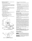
HEATING, CONSTANT VOLUME (CV) UNITS — The
control module is powered by 24 vac. If the unit is con-
trolled with a room sensor, the fan will run continuously in
the Occupied mode, with the outside-air damper in the mini-
mum position. If the unit is controlled through a room ther-
mostat (with FAN set to AUTO), upon a call for heat the first
stage of heat is energized, the indoor-fan motor will turn on,
and the outdoor-air damper will move to the minimum po-
sition. Upon a call for additional heat (if the unit is equipped
with a two-stage heater), the second stage of heat is ener-
gized. When the call for heat is satisfied, the heaters will
deenergize. The indoor-fan motor will also deenergize (un-
less controlled by a room sensor) and the outdoor-air damper
will move to the closed position.
If the unit is controlled with a room sensor the fan will not
run in the unoccupied mode. Upon a call for heat, the first
stage of heat is energized, the indoor-fan motor will turn on,
and the outdoor air damper will move to the Unoccupied
IAQ position (generally set to zero in the unoccupied mode).
The IAQ feature is enabled through system software. Upon
a call for additional heat (if the unit is equipped with a two-
stage heater), the second stage of heat is energized. When
the call for heat is satisfied, the heaters and indoor-fan motor
will deenergize and the outdoor-air damper will move to the
closed position (if open).
HEATING, VARIABLE AIR VOLUME (VAV) UNITS —
The control board is powered by 24 vac. When there is a call
for heating (from Morning Warm-Up, Unoccupied, or Oc-
cupied modes), power is sent from the control module to
energize the first stage of electric heat. A field-supplied heat
40