


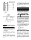
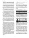

Minimum Damper Position Setting — Setting of the out-
door air damper position is performed in conjunction with a
shortened version of the field-run test. This is performed by
first opening DIP (Dual In-Line Package) switch no. 6 then
no. 4. See Fig. 17 and Table 7.
The outdoor-air damper closes. The control allows 90 sec-
onds for the damper to close in case it is in the full open
position. Next, the indoor-fan contactor will energize. The
outdoor-air damper will remain at 0% for 30 seconds. It will
then move to the 10% position for another 30 seconds. This
will be repeated at every 10% increment for 30 seconds until
the damper reaches 100% open. Close DIP switch no. 6 dur-
ing the 30 seconds immediately after the desired outdoor air
minimum damper position. The 30-second time period is to
allow time where DIP switch no. 6 can be closed. The de-
fault value of the minimum outdoor air damper position is
20%. If the desired minimum position is 30%, allow the damper
position to go to 10% for 30 seconds, then 20% for 30 sec-
onds, and when it reaches 30% close DIP switch no. 6 dur-
ing the 30-second period following the 30% position.
The minimum outdoor air damper position is now set.
ECONOMIZER SETTINGS
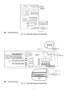
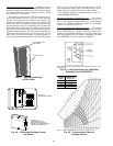
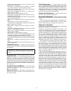
Accessory Enthalpy Control (Fig. 28) — The control
(HH57AC077) is mounted in the economizer hood. See
Fig. 19. The enthalpy setting adjustment is on the enthalpy
control. For maximum benefit of outdoor air, set enthalpy
control to A. See Fig. 29 and 30.
Accessory Differential Enthalpy Control — The control
(HH57AC077), in conjunction with the accessory enthalpy
sensor (HH57AC078), controls economizer operation ac-
cording to the differential enthalpy. The control is mounted
in the economizer hood. The sensor is mounted in the return
duct (50EJ/EK) or return air plenum (50EW/EY).
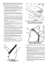
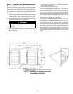
BLACK SEAL STRIP
(CENTERED)
FILTER COVER
Fig. 27 — Attaching Seal Strip
to Filter Cover
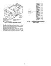
Fig. 28 — Differential Enthalpy Control
and Sensor
HH57AC077
ENTHALPY CONTROL
HH57AC078
ENTHALPY SENSOR
(USED WITH ENTHALPY
CONTROL FOR DIFFERENTIAL
ENTHALPY OPERATION)
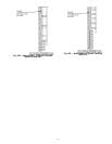
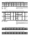
NOTE: Switches shown in high enthalpy state. Terminals 2 and 3 close on en-
thalpy decrease.
Fig. 29 — Wire Connections for Solid State
Enthalpy Control (HH57AC077)
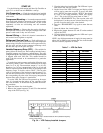
RH — Relative Humidity
Fig. 30 — Psychrometric Chart for
Enthalpy Control
CONTROL
CURVE
CONTROL POINT
(APPROX. DEG.)
AT 50% RH
A 73 (23)
B 70 (21)
C 67 (19)
D 63 (17)
+
C7400A1004
28