


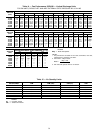


CAPACITY CONTROL, COOLING — The cooling capac-
ity staging tables are shown in Tables 18 and 19.
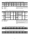
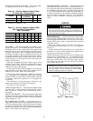
Table 18 — Cooling Capacity Staging Table
CV Units with 2 Compressors
STAGES 0
1
ECONOMIZER
23
Compressor 1 Off Off On On
Compressor 2 Off Off Off On
NOTE: OnCV units thatrequire additional unloading,add suction pres-
sure unloaders on Compressor 1 only.
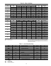
Table 19 — Cooling Capacity Staging Table
VAV Units with 2 Compressors
and 2 Unloaders*
STAGES 0 123456
Compressor 1 OffOnOnOnOnOnOn
Unloader 1 Off On On Off On On Off
Unloader 2 Off On Off Off On Off Off
Compressor 2 Off Off Off Off On On On
*40 ton units have only 1 unloader.
FIELD TEST — The field test program is initiated by mov-
ing up DIP switch no. 4 to the OPEN position. The outdoor-
air damper will close. The control allows 90 seconds for the
damper to close in case it was in the full open position. Next,
the indoor-fan contactor will be energized, and the outside-
air damper will begin to open to its default value of 20% and
stay at that position for a short period of time. The outdoor-
air damper will then open to its full open position and stay
at that position for a short period of time. The outdoor-air
damper will then close.
If the unit is equipped with power exhaust, stage 1 will be
energized for 5 seconds. If the unit is configured for stage 2
of power exhaust, stage 2 will be energized for 5 seconds
after the first stage is deenergized.
The first stage of heat will be energized for 30 seconds,
after which the second stage heat will be energized for an
additional 30 seconds. Heat is then deenergized.
The last step is the Cooling mode. Outdoor-fan contactor
no. 1 is energized. This is followed by each stage of cooling
energized with a 10-second delay between stages. After this
is complete, outdoor-fan contactor no. 2 is energized for
10 seconds.
The compressors will now deenergize, followed by the
outdoor-fan contactors and indoor-fan contactors.
The field test is then complete.
TIME GUARD CIRCUIT — The Time Guard function (built
into the rooftop’s control module board) maintains a mini-
mum off time of 5 minutes and a minimum on time of
10 seconds.
CRANKCASE HEATER —The unit main power supply must
remain on to provide crankcase heater operation. The crank-
case heater in each compressor keeps oil free of refrigerant
while compressor is off.
HEAD PRESSURE CONTROL — Each unit has a fan cy-
cling, outdoor thermostat to shut off outdoor-fan motor(s) at
55 F (one outdoor-fan motor on 024-034 units and 2 outdoor-
fan motors on 038-048 units). The head pressure control per-
mits the unit to operate with correct condensing temperatures
down to 35 F outdoor-air temperature.
MOTORMASTER III DEVICE — The Motormaster III
Solid-State Head Pressure Control is a field-installed acces-
sory, fan speed control device actuated by a temperature sen-
sor. The Motormaster III device is specifically designed for
use on Carrier equipment and controls the outdoor-fan mo-
tor speed in response to the saturated condensing tempera-
ture. For outdoor temperatures down to −20 F, the Motor-
master III device maintains condensing temperature at
100 F.
SERVICE
Before performing service or maintenance operations on
unit, turn off main power switch to unit. Turn off ac-
cessory heater power switch if applicable. Electrical shock
could cause personal injury.
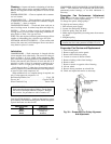
Service Access — All unit components can be reached
through clearly labelled hinged access doors. These doors
are not equipped with tiebacks, so if heavy duty servicing is
needed, either remove them or prop them open to prevent
accidental closure.
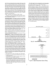
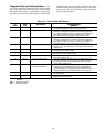
Each door is held closed with 3 latches. The latches are
secured to the unit with a single
1
⁄
4
-in.-20x
1
⁄
2
-in. long bolt.
See Fig. 37.
To open, loosen the latch bolt using a
7
⁄
16
-in. wrench. Pivot
the latch so it is not in contact with the door. Open the door.
To shut, reverse the above procedure.
NOTE: Disassembly of the top cover may be required under
special service circumstances. It is very important that the
orientation and position of the top cover be marked on the
unit prior to disassembly. This will allow proper replace-
ment of the top cover onto the unit and prevent rainwater
from leaking into the unit.
IMPORTANT: After servicing is completed, make sure
door is closed and relatched properly, and that the latches
are tight. Failure to do so can result in water leakage
into the evaporator section of the unit.
Fig. 37 — Door Latch
42