


interlock relay signals for the air terminals to fully open. See
Fig. 35. In the Occupied mode, the indoor-fan motor will
operate continuously and the outdoor-air dampers will be in
the minimum position. In the Unoccupied mode, the indoor-
fan motor will be off, but will energize upon the call for heat.
The outdoor-air dampers will move to the IAQ unoccupied
position (generally set to zero in the Unoccupied mode). The
IAQ feature is enabled through system software. The duct
pressure sensor will signal to the variable frequency drive to
operate at full speed. Upon a call for additional heat (if the
unit is equipped with a two-stage heater), the second stage
of heat will be energized. When the call for heat is satisfied,
the heaters will deenergize.
NOTE: The HIR is not needed in a DAV system.
If the unit is in the Unoccupied mode, the indoor-fan mo-
tor will deenergize and the outdoor-air damper will move to
the closed position (if open).
MORNING WARM-UP (VAV ONLYWITH PC ACCESSED/
CCN OPERATION) — Morning warm-up occurs when the
control module has been programmed to turn on heat, prior
to the Occupied mode, to be ready for the occupancy. Morn-
ing warm-up is a condition in VAV systems that occurs when
the Temperature Compensated Start algorithm calculates a
biased occupied start time and the unit has a demand for heat-
ing. The warm-up will continue into the occupied period as
long as there is a need for heat. During warm-up, the unit
can continue heating into the occupied period, even if oc-
cupied heating is disabled. When the heating demand is sat-
isfied, the warm-up condition will terminate. To increase or
decrease the heating demand, use the network access soft-
ware to change the occupied heating set point.
NOTE: To utilize morning warm-up mode, the unit occu-
pancy schedule must be accessed via Service Tool, Comfort
Works, or Building Supervisor software (units running Ver-
sion 1.0 of unit control software).
MORNING WARM-UP (VAVONLYWITH STAND-ALONE
OPERATION) — When a unit running version 2.0 of the
unit control software operates in stand-alone mode, morning
warm-up occurs when the unit is energized in Occupied mode
and return-air temperature (RAT) is below 68 F. Warm-up
will not terminate until the RAT reaches 68 F. The heat in-
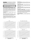
terlock relay output is energized during morning warm-up.
(A field-installed 24-vdc heat interlock relay is required.) The
output will be energized until the morning warm-up cycle is
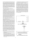
complete. Refer to Fig. 35 for heat interlock relay wiring.
SPACE TEMPERATURE RESET (VAV ONLY) — An ac-
cessory space temperature sensor is required. Space tem-
perature reset is used to reset the supply-air temperature set
point of a VAV system higher, as the space temperature falls
below the Occupied Cool set point. As the space tempera-
ture falls below the cool set point, the supply-air tempera-
ture will be reset upward as a function of the reset ratio. Re-
set ratio is expressed in degrees change in supply-air temperature
per degree of space temperature change. A reset limit will
exist which will limit the maximum number of degrees the
supply-air temperature may be raised. Both the reset ratio
and the reset limit are user definable. The sequence of op-
eration is as follows:
1. The on/off status of the unit supply fan is determined.
2. If the fan is on, the sequence will check if the system is
in Occupied mode.
3. If the system is in Occupied mode, the sequence will de-
termine if the reset option is enabled.
4. If the reset option is enabled, the sequence will read the
space temperature and compare it to the Occupied Cool
set point. If the temperature is below the Occupied Cool
set point, the algorithm will compute the reset value and
compare this value against the reset limit. If it is greater
than the reset limit, the sequence will use the reset limit
as the reset value.
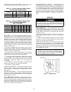
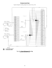
The field-supplied space temperature sensor input signal
(4 to 20 ma and 2 to 10 vdc) enables the space temperature
reset function. Refer to Fig. 36 for sensor wiring.
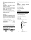
POWER EXHAUST OPERATION — The optional power
exhaust packages are factory- or field-installed with vertical
units and optionally installed in the return air ductwork for
horizontal applications. The standard (only offered with con-
stant volume units) and modulating power exhaust (offered
on VAV units) are the 2 packages available. The modulating
power exhaust package is equipped with a field-adjustable
static pressure controller which will control up to 4 power
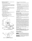
exhaust stages to maintain a building static pressure. The blue
sequencer located in the control box below the control board
can be adjusted by removing the covers and adjusting the set
point dial to the desired building pressure. The standard power
exhaust package controls up to 2 stages of power exhaust to
maintain building pressure. These power exhaust stages are
staged according to a percentage of the economizer damper
position. The default values are 25% for Stage 1 and 75%
for Stage 2. This package has set points that are adjustable
through software (such as Service Tool, Building Supervi-
sor, or Comfort Works).
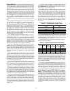
Fig. 35 — Heat Interlock Relay Wiring
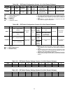
Fig. 36 — Space Temperature Sensor Wiring
41