


Remote Field Control (Units Running Version 2.0 of Unit
Control Software) — A switch closure across terminals R
and W1 on TB-3 will initiate the Occupied mode. This can
be done manually as well as through a field-supplied
timeclock.
Service Tool, Building Supervisor, and Comfort Works —
Access to the control board can be achieved through the ter-
minal marked CCN via a 3-wire bus.
IMPORTANT: Default bus address is 0. Default ele-
ment number is 1. Refer to CCN literature for infor-
mation on network addressing or changing CCN com-
munication defaults.
Carrier Comfort Network Interface — The 50E units can be
connected to the CCN. The communication bus wiring is sup-
plied and installed in the field. Wiring consists of shielded,
3-conductor cable with drain wire.
The system elements are connected to the communication
bus in a daisy chain arrangement. The positive pin of each
system element communication connector must be wired to
the positive pins of the system element on either side of it,
the negative pins must be wired to the negative pins, and the
signal pins must be wired to signal ground pins. Wiring con-
nections for CCN should be made at the 3-pin plug (CCN
located at the base board. Consult CCN literature for further
information.
Conductors and drain wire must be 20 AWG minimum
stranded, tinned copper. Individual conductors must be in-
sulated with PVC, PVC/nylon, vinyl, Teflon, or polyethyl-
ene. An aluminum/polyester 100% foil shield and an outer
jacket of PVC, PVC/nylon, chrome vinyl, or Teflon with a
minimum operating temperature range of −20 C to 60 C
(−4 F to 140 F) is required. Table 5 lists cables that meet the
requirements.
Table 5 — CCN Connection Approved
Shielded Cables
MANUFACTURER CABLE PART NO.
Alpha 2413 or 5463
American A22503
Belden 8772
Columbia 02525
IMPORTANT: When connecting the CCN communi-
cation bus to a system element, use a color coding sys-
tem for the entire network to simplify installation and
checkout. See Table 6.
Table 6 — Color Code Recommendations
SIGNAL
TYPE
CCN BUS CONDUCTOR
INSULATION COLOR
CCN PLUG
PIN NO.
Positive (+) RED 1
Ground WHITE 2
Negative (−) BLACK 3
NOTE: If a cable with a different color scheme is selected,
a similar color code should be adopted for the entire network.
At each system element, the shields of the communica-
tion bus cables must be tied together. If the communication
bus is entirely within one building, the resulting continuous
shield must be connected to a ground at one point only.If
the communication bus cable exits from one building and
enters another, the shields must be connected to grounds at
the lightning suppressor in each building where the cable
enters or exits the building (one point per building only).
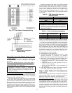
To connect the unit to the network:
1. Turn off power to the control box.
2. Cut the CCN wire and strip the ends of the red (+), white
(ground), and black (−) conductors. (If a different
network color scheme is used, substitute appropriate colors.)
3. Remove the 3-pin male plug from the base module in the
main control box, and connect the wires as follows:
a. Insert and secure the red (+) wire to terminal 1 of the
3-pin plug.
b. Insert and secure the white (ground) wire to ter-
minal 2 of the 3-pin plug.
c. Insert and secure the black (−) wire to terminal 3 of
the 3-pin plug.
4. Insert the plug into the existing 3-pin mating connector
on the base module in the main control box.
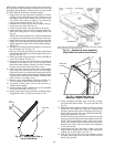
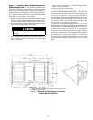
Step 8 — Make Outdoor-Air Inlet Adjustments
ECONOMIZER
NOTE: If accessory power exhaust or barometric relief pack-
ages are being added to the unit, install power exhaust or
barometric relief before installing economizer hoods.
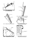
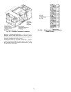
Economizer Hood Assembly — The economizer hood is
shipped in a package secured to the outside of the unit and
must be field-assembled. There are 2 hoods on every unit.
The 50EW/EY units are side supply and side return. The re-
turn duct limits access to economizer filters from below. Fil-
ter tracks (mounting angle without tabs) must be installed
correctly to allow access to economizer filters from each side.
Perform the following procedure to assemble the econo-
mizer hood.
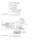
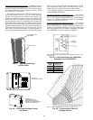
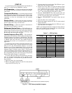
Fig. 16 — Field Control Thermostat Wiring
Fig. 17 — Field Control Temperature
Sensor Wiring
NOTE:Sensor partnumbersare
as follows:
T55 — HH51BX001
T56 — HH51BX004
T57 — CEC01215303-01
NOTE: On units running Version 1.0 of
theunit controlsoftware, theremotestart/
stop switch is connected to R and Y1.
25