


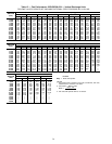
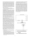
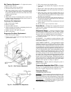

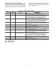

Belt Tension Adjustment — To adjust belt tension:
1. Remove power to unit.
2. Remove motor mount nuts and bolts.
3. Loosen fan motor nuts. See Fig. 39.
4. Turn motor jacking bolts to move motor mounting plate
left or right for proper belt tension. A slight bow should
be present in the belt on the slack side of the drive while
running under full load.
5. Tighten nuts.
6. Adjust bolts and nut on mounting plate to secure motor
in fixed position. Recheck belt tension after 24 hours of
operation. Adjust as necessary.
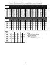
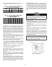
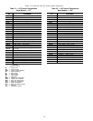
Condenser-Fan Adjustment
1. Shut off unit power supply.
2. Remove fan guard.
3. Loosen fan hub setscrews.
4. Adjust fan height on shaft using a straightedge placed across
venturi and measure per Fig. 40.
5. Tighten setscrews and replace fan guard.
6. Turn on unit power.
Evaporator-Fan Motor Replacement
1. Shut off unit power supply.
2. Remove upper outside panel and open hinged door to
gain access to motor.
3. Fully retract motor plate adjusting bolts.
4. Loosen the 2 rear (nearest the evaporator coil) motor
plate nuts.
5. Remove the 2 front motor plate nuts and carriage bolts.
6. Slide motor plate to the rear (toward the coil) and re-
move fan belt(s).
7. Slide motor plate to the front and hand tighten one of
the rear motor plate nuts (tight enough to prevent the
motor plate from sliding back but loose enough to allow
the plate to pivot upward).
8. Pivot the front of the motor plate upward enough to al-
low access to the motor mounting hex bolts and secure
in place by inserting a prop.
9. Remove the nuts from the motor mounting hex bolts and
remove motor.
10. Reverse above steps to install new motor.
Power Failure — Dampers have a spring return. In event
of power failure, dampers will return to fully closed position
until power is restored.
Refrigerant Charge — Amount of refrigerant charge
is listed on unit nameplate and in Table 1. Refer to Carrier
GTAC II; Module 5; Charging, Recovery, Recycling, and Rec-
lamation section for charging methods and procedures.
Unit panels must be in place when unit is operating dur-
ing charging procedure.
NO CHARGE — Use standard evacuating techniques. After
evacuating system, weigh in the specified amount of refrig-
erant (refer to Table 1).
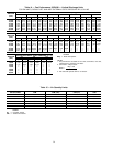
LOW CHARGE COOLING — Using appropriate cooling
charging chart (see Fig. 41 and 42), add or remove refrig-
erant until conditions of the appropriate chart are met. Note
that charging chart is different from those normally used.An
accurate pressure gage and temperature sensing device are
required. Measure liquid line pressure at the liquid line serv-
ice valve using pressure gage. Connect temperature sensing
device to liquid line near the liquid line service valve and
insulate it so that outdoor ambient temperature does not af-
fect reading. Indoor-air cfm must be within normal operat-
ing range of unit. Take outdoor ambient temperature and read
the suction pressure gage. Refer to appropriate chart to de-
termine correct suction temperature. If intersection point on
chart is above the curve, add refrigerant. If intersection point
on chart is below curve, carefully recover some of the charge.
Recheck suction pressure as charge is adjusted.
Filter Drier — Replace whenever refrigerant system is
exposed to atmosphere.
Thermostatic Expansion Valve (TXV) — Each cir-
cuit has one. It is nonadjustable and is factory set to main-
tain 10 to 13° F superheat leaving the evaporator coil. Con-
trols flow of liquid refrigerant to the evaporator coils.
Protective Devices
COMPRESSOR PROTECTION
Overcurrent — Each compressor has one manual reset, cali-
brated trip, magnetic circuit breaker. Do not bypass connec-
tions or increase the size of the circuit breaker to correct trouble.
Determine the cause and correct it before resetting the breaker.
Overtemperature — Each 06D type compressor (024-038 units
only) has an internal protector to protect it against exces-
sively high discharge gas temperatures.
Fig. 39 — Belt Tension Adjustment
Fig. 40 — Condenser-Fan Adjustment
44