


Features with sensor control of unit with computer access
are:
• 365 day timeclock with backup (supports minute, hour,
day of week, date, month, and year)
• daylight savings time function
• occupancy control with 8 periods for unit operation
• holiday table containing up to 18 holiday schedules
• ability to initiate timed override from T-55 or T-56 sensors
• ability to use multiple space temperature sensors to aver-
age the space temperature
• supply air temperature reset for the supply air temperature
set point
• temperature compensated start to calculate early start times
before occupancy
• access to the Display, Maintenance, Configuration, Serv-
ice, and Set Point data table through network software
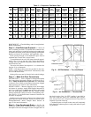
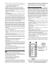
When the unit is equipped with a field-supplied space tem-
perature sensor and a remote contact closure (remote start/
stop) on the base control board, the occupied default set points
will monitor unit operation. The occupied default set points
are 78 F cooling and 68 F heating (if electric heat is in-
stalled). See Fig. 11 for remote start/stop wiring.
NOTE: For units which have not had the base unit control
board accessed via software to set an occupancy schedule,
the remote start/stop closure will allow the unit to operate in
the pre-configured occupied default set points (based on return-
air temperature) of 78 F cooling and 68 F heating. Without
this feature, the unit will control to the unoccupied default
set points of 90 F cooling and 55 F heating (if electric heat
is installed).
An electronic expansion board may be field-installed to
provide the following features:
• control of modulating economizer damper to maintain
indoor air quality (IAQ) when outdoor conditions are
suitable
• provide discrete inputs for fan status, filter status, field-
applied status, and demand limit
• provide an output for the external alarm light indicator
When the unit is connected to the CCN (Carrier Comfort
Network), the following expansion board features can be
utilized.
• perform Demand Limit functions based on CCN loadshed
commands or the state of the discrete input
• alarm monitoring of all key parameters
• CCN protocol
• provides power exhaust fire outputs for direct control of
modulated power exhaust stages during fire or smoke modes
• smoke control modes including evacuation, smoke purge,
pressurization, and fire shutdown (modulating power ex-
haust required)
• provides CCN IAQ participation
See Carrier TEMP or VVT (Variable Volume and Tem-
perature) literature for complete TEMP (single zone) or VVT
(multi-zone) application information.
Features with Sensor Control of Unit (Network Applica-
tions) — The base control board provides, as standard, a con-
nection for use with a Carrier VVT system and can also be
integrated into a Carrier Comfort Network.
When the unit is accessed via a PC equipped with Com-
fort Works, Building Supervisor, or Service Tool, the fol-
lowing features can be accessed:
• on-board timeclock can be programmed
• occupancy schedules can be programmed
• unit set points can be changed
• alarms can be monitored
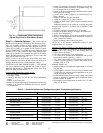
This access is available on the base control board via a
RJ-11 phone jack or a 3-wire connection to the communi-
cation bus. See Fig. 12. The timeclock has a 10-hour minimum
back-up time to provide for unit power off for servicing unit
or during unexpected power outages. For complete Carrier
Comfort System (CCS) or Carrier Comfort Network (CCN)
features and benefits, refer to the product literature.
VARIABLE AIR VOLUME (VAV) APPLICATIONS
Features with Stand-Alone Applications — A VAV unit is
capable of providing unoccupied cooling controlling to a
90 F return-air temperature utilizing the factory-supplied return-
air thermistor located below the return-air damper in the return-
air section for unit control. The unit will provide unoccupied
heating (if electric heat is installed) controlling to a 55 F
return-air temperature. Also provided is a morning warm-up
which is initiated by the Occupied mode (if electric heat is
installed) and continues until the return-air temperature rises
to 68 F. The unit will provide occupied cooling with a de-
fault temperature of 55 F for the supply air. The supply-air
temperature is measured by the supply-air thermistor, lo-
cated in the indoor fan compartment.
Standard features of a VAV unit with a remote start/stop
switch are:
• control of an outdoor condenser fan based upon outdoor
air temperature
• control of modulating economizer to provide free cooling
when outdoor conditions are suitable, using supply air tem-
perature as a set point
• support of remote occupied/unoccupied input to start or
stop the unit
• provide power exhaust output to an external power ex-
haust controller
• support supply air temperature reset to offset supply air
set point
• support a field test for field check out
• support linkage to DAV systems
• cooling capacity control of 6 stages plus economizer with
compressors and unloaders to maintain supply air tem-
perature set point during occupied periods
• control of one stage of heat to maintain supply air tem-
perature at supply air set point during occupied periods
• provide a variable frequency drive high voltage relay out-
put to enable VFD
• control of heat interlock relay
With the addition of a remote start/stop switch heating or
cooling is enabled during unoccupied periods as required to
maintain space temperature to within unoccupied set points.
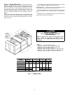
NOTE: On units running Version 1.0 of the Unit Control Software, the remote
start/stop switch is connected to R andY1. On units running Version 2.0 of the
Unit Control Software, the remote start/stop switch is connected to R and W1.
Fig. 11 — Field Control Remote Start/Stop
13