


START-UP
Use the following information and Start-Up Checklist on
page CL-1 to check out unit PRIOR to start-up.
Unit Preparation — Check that unit has been installed
in accordance with these installation instructions and appli-
cable codes.
Compressor Mounting — Loosen the compressor hold-
down bolts until sidewise movement of the washer under
each holddown bolt head can be obtained. Do not loosen
completely as bolts are self-locking and will maintain
adjustment.
Service Valves — Ensure that the suction, discharge,
and liquid line service valves are open. Damage to the com-
pressor could result if they are left closed.
Internal Wiring — Check all electrical connections in
unit control boxes; tighten as required.
Refrigerant Service Ports — Each refrigerant sys-
tem has one suction port located in the top of the compressor
motor casing. All units also have one service port on the liq-
uid line valve and one on the compressor discharge valve.
Be sure that caps on the ports are tight.
Variable Frequency Drive (VFD) — The variable fre-
quency drives are factory set. These settings include factory-
installed jumpers and software configurations. The only
configured set point is duct static pressure.An Operation Manual
is shipped with each VAV unit. This manual should be
used if the drive needs to be customized for a particular
application.
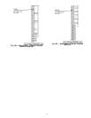
To set the duct static pressure, perform the following steps.
The factory setting is zero. The duct transducer has a range
from 0 to 5 in. wg. The transducer output is 2 to 10 vdc,
therefore, 0 to 5 in. wg is proportional to the 2 to 10 vdc and
must be expressed to the VFD in terms of percentage of the
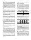
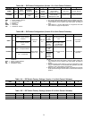
frequency range. To do this, refer to Table 7. The set point
value is a percentage of the maximum output frequency. Lo-
cate the duct static pressure closest to that desired and use
the corresponding set point value. If necessary, interpolation
between duct static pressures is permissible.
To set the VFD, the VFD must be powered up, however,
since it is located near the indoor air fan, operation of the
fan is not desirable. To disable the fan, perform the follow-
ing procedure:
1. Open the indoor fan circuit breaker.
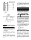
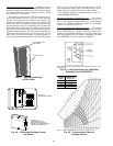
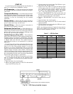
2. Remove the jumper between CC and ST on the terminal
strip of the VFD (see Fig. 34).
3. Close the indoor fan circuit breaker. The VFD now is pow-
ered but the fan will not operate.
4. On the front of the VFD is a keypad and display which
will be used to enter the set point. To access this field,
press ‘‘SETUP’’ key, then press the ‘‘SETUP’’key 6 times
to scroll to the sixth parameter, which will display
‘‘Sr1.’’ This is the VFD set point listed in Table 7.
5. Press the ‘‘READ/WRITE’’ key. The set point value will
be displayed. Use the up-arrow or down-arrow key to ad-
just the set point value to the value desired.
6. Press the ‘‘READ/WRITE’’ key again to enter the new
value.
7. Open the indoor fan circuit breaker.
8. Replace the jumper between CC and ST on the terminal
strip of the VFD.
9. Close the indoor fan circuit breaker, the VFD now is pow-
ered and the fan will operate.
NOTE: Any field measurement of supply fan amps must be
taken with an RMS meter between the fan circuit breaker
and fan contactor (upstream of VFD).
Table 7 — VFD Set Point
PRESSURE
(in. wg)
VOLTAGE
(vdc)
VFD
SET POINT
0.00 2.0 12.0
0.25 2.4 14.4
0.50 2.8 16.8
0.75 3.2 19.2
1.00 3.6 21.6
1.25 4.0 24.0
1.50 4.4 26.4
1.75 4.8 28.8
2.00 5.2 31.2
2.25 5.6 33.6
2.50 6.0 36.0
2.75 6.4 38.4
3.00 6.8 40.8
3.25 7.2 43.2
3.50 7.6 45.6
VFD — Variable Frequency Drive
NOTE: Terminal strip is located inside the VFD (Variable Frequency
Drive) at the bottom.
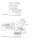
Fig. 34 — VFD Factory-Installed Jumpers
32