


Condenser Coil, Evaporator Coil, and Conden-
sate Drain Pan —
Inspect the condenser coil, evapo-
rator coil, and condensate drain pan at least once each year.
Proper inspection and cleaning requires the removal of the
unit top. See Unit Top Removal section on page 45.
The coils are easily cleaned when dry; therefore, inspect
and clean the coils either before or after each cooling sea-
son. Remove all obstructions, including weeds and shrubs,
that interfere with the airflow through the condenser coil.
Straighten bent fins with a fin comb. If coated with dirt or
lint, clean the coils with a vacuum cleaner, using the soft
brush attachment. Be careful not to bend the fins. If coated
with oil or grease, clean the coils with a mild detergent-and-
water solution. Rinse coils with clear water, using a garden
hose. Be careful not to splash water on motors, insulation,
wiring, or air filter(s). For best results, spray condenser coil
fins from inside to outside the unit. On units with an outer
and inner condenser coil, be sure to clean between the coils.
Be sure to flush all dirt and debris from the unit base.
Inspect the drain pan and condensate drain line when in-
specting the coils. Clean the drain pan and condensate drain
by removing all foreign matter from the pan. Flush the pan
and drain tube with clear water. Do not splash water on the
insulation, motor, wiring, or air filter(s). If the drain tube is
restricted, clear it with a ‘‘plumbers snake’’ or similar probe
device. Ensure that the auxiliary drain port above the drain
tube is also clear.
Condenser Fan
Keep the condenser fan free from all obstructions to en-
sure proper cooling operation. Never place articles on
top of the unit. Damage to unit may result.
1. Remove 2 screws at bottom and 2 screws along sides of
condenser air intake grille and remove plastic grille.
2. Inspect the fan blades for cracks or bends.
3. If fan needs to be removed, loosen the setscrew and slide
the fan off the motor shaft.
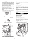
4. When replacing fan blade, position blade so that lead-
ing edge is
1
⁄
2
in. in front of fan orifice. See Fig. 23.
5. Ensure that setscrew engages the flat area on the motor
shaft when tightening.
6. Replace grille.
Electrical Controls and Wiring — Inspect and check
the electrical controls and wiring annually. Be sure to turn
off the gas supply, and then the electrical power to the unit.
Remove the control, blower, and compressor compart-
ment access panels to locate all the electrical controls and
wiring. Check all electrical connections for tightness. Tighten
all screw connections. If any smoky or burned connections
are noticed, disassemble the connection, clean all the parts,
restrip the wire end and reassemble the connection properly
and securely.
After inspecting the electrical controls and wiring, re-
place all the panels. Start the unit, and observe at least one
complete heating cycle and one complete cooling cycle to
ensure proper operation. If discrepancies are observed in ei-
ther or both operating cycles, or if a suspected malfunction
has occurred, check each electrical component with the proper
electrical instrumentation. Refer to the unit wiring label when
making these checkouts.
NOTE: Refer to the heating and/or cooling sequence of op-
eration in this publication as an aid in determining proper
control operation.
Refrigerant Circuit — Inspect all refrigerant tubing con-
nections and the unit base for oil accumulations annually.
Detecting oil generally indicates a refrigerant leak.
If oil is detected or if low cooling performance is sus-
pected, leak-test all refrigerant tubing using an electronic leak-
detector, halide torch, or liquid-soap solution. If a refriger-
ant leak is detected, refer to Check for Refrigerant Leaks
section on page 23.
If no refrigerant leaks are found and low cooling perfor-
mance is suspected, refer to Checking and Adjusting Refrig-
erant Charge section on page 35.
Gas Input — The gas input does not require checking
unless improper heating performance is suspected. If a prob-
lem exists, refer to Start-Up section on page 23.
Evaporator Airflow — The heating and/or cooling air-
flow does not require checking unless improper perfor-
mance is suspected. If a problem exists, be sure that all supply-
and return-air grilles are open and free from obstructions,
and that the air filter is clean. When necessary, refer to Evapo-
rator Airflow and Airflow Adjustments section on page 35 to
check the system airflow.
Metering Device — Acutrol™ Device — This me-
tering device is a fixed orifice and is located in the header to
the evaporator coil.
Liquid Line Strainer — The liquid line strainer (to pro-
tect metering device) is made of wire mesh and located in
the liquid line on the inlet side of the metering device.
47