


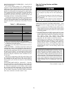
HEAT ANTICIPATOR SETTING — The room thermostat
heat anticipator must be properly adjusted to ensure proper
heating performance. Set the heat anticipator, using an am-
meter between the W and R terminals to determine the
exact required setting.
NOTE: For thermostat selection purposes, use 0.18 amp for
the approximate required setting.
Failure to make a proper heat anticipator adjustment will
result in improper operation, discomfort to the occupants of
the conditioned space, and inefficient energy utilization; how-
ever, the required setting may be changed slightly to provide
a greater degree of comfort for a particular installation.
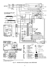
TRANSFORMER PROTECTION — The unit transformer
protection may be one of 2 types.
The first transformer type may contain an auto. reset over-
current protector for control circuit protection. If this device
trips, it may reset without warning, starting the heating or
cooling section of this product. Use caution when servicing;
if overcurrent protector continues to trip, there is a problem
in the low-voltage electrical circuit, such as an electrical short,
ground, or transformer overload. Disconnect power, correct
the condition, and check for normal unit operation.
The second transformer type is of the energy-limiting type.
It is set to withstand a 30-second overload or shorted
secondary condition.
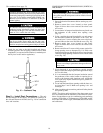
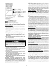
PRE-START-UP
Failure to observe the following warnings could result
in serious personal injury:
1. Follow recognized safety practices and wear protec-
tive goggles when checking or servicing refrigerant
system.
2. Do not operate compressor or provide any electric
power to unit unless compressor terminal cover is in
place and secured.
3. Do not remove compressor terminal cover until all
electrical sources are disconnected.
4. Relieve and reclaim all refrigerant from system be-
fore touching or disturbing anything inside terminal
box if refrigerant leak is suspected around compres-
sor terminals.
5. Never attempt to repair soldered connection while re-
frigerant system is under pressure.
6. Do not use torch to remove any component. System
contains oil and refrigerant under pressure. To re-
move a component, wear protective goggles and pro-
ceed as follows:
a. Shut off gas supply and then electrical power to
unit.
b. Relieve and reclaim all refrigerant from system
using both high- and low-pressure ports.
c. Cut component connecting tubing with tubing cut-
ter and remove component from unit.
d. Carefully unsweat remaining tubing stubs when
necessary. Oil can ignite when exposed to torch
flame.
Proceed as follows to inspect and prepare the unit for ini-
tial start-up:
1. Remove all access panels.
2. Read and follow instructions on all WARNING, CAU-
TION, and INFORMATION labels attached to, or shipped
with, unit.
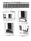
3. Make the following inspections:
a. Inspect for shipping and handling damages such as bro-
ken lines, loose parts, disconnected wires, etc.
b. Inspect for oil at all refrigerant tubing connections and
on unit base. Detecting oil generally indicates a re-
frigerant leak. Leak-test all refrigerant tubing connec-
tions using electronic leak detector, halide torch, or
liquid-soap solution. If a refrigerant leak is detected,
see Check for Refrigerant Leaks section on page 23.
c. Inspect all field- and factory-wiring connections. Be
sure that connections are completed and tight.
d. Inspect coil fins. If damaged during shipping and han-
dling, carefully straighten fins with a fin comb.
4. Verify the following conditions:
Do not purge gas supply into the combustion cham-
ber. Do not use a match or other open flame to check
for gas leaks. Failure to follow this warning could
result in an explosion causing personal injury or death.
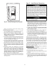
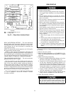
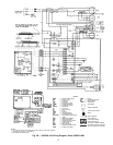
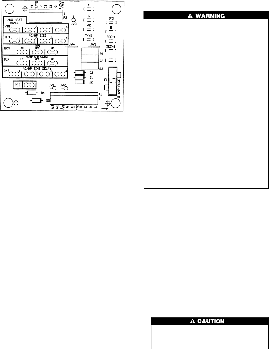
LEGEND
IFO — Indoor (Evaporator) Fan On
JW — Jumper Wire
Fig. 22 — Easy Select Interface Board
22