


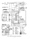
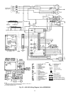
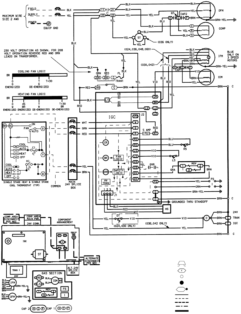
LEGEND
AWG — American Wire Gage
BR — Blower Relay
C—Contactor
CAP — Capacitor
COMP — Compressor Motor
CR — Combustion Relay
DT — Discharge Thermostat
EQUIP — Equipment
FL — Fuse Link
FS — Flame Sensor
FU — Fuse
GND — Ground
GVR — Gas Valve Relay
HS — Hall Effect Sensor
HV TRAN — High-Voltage Transformer
I—Ignitor
IDM — Induced-Draft Motor
IFM — Indoor-Fan Motor
IGC — Integrated Gas Control
LS — Limit Switch
MGV — Main Gas Valve
NEC — National Electrical Code
OFM — Outdoor-Fan Motor
PWR — Power
QT — Quadruple Terminal
RS — Rollout Switch
ST — Start Thermistor
TRAN — Transformer
Field Splice
Terminal (Marked)
Terminal (Unmarked)
Splice
Splice (Marked)
Factory Wiring
Field Control Wiring
Field Power Wiring
Accessory or Optional Wiring
To Indicate Common Potential
Only, Not to Represent Wiring
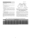
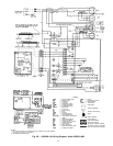
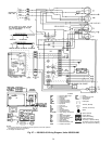
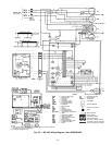
NOTES:
1. If any of the original wire furnished must be replaced, it must be
replaced with type 90 C wire or its equivalent.
2. Use copper conductors only.
Fig. 29 — 208/230-1-60 Wiring Diagram, Units 48SX024-042
30