


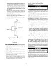
Measure Manifold Pressure (Propane Units) — The main burner
orifices on a propane gas unit are sized for the unit rated
input when the manifold pressure reading matches the level
specified in Table 5.
Proceed as follows to adjust gas input on a propane gas
unit:
1. Turn off gas to unit.
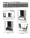
2. Remove pipe plug on manifold (see Fig. 24), then con-
nect manometer at this point.
3. Turn on gas to unit.
4. Remove cover screw over regulator adjustment screw on
gas valve.
5. Adjust regulator adjustment screw to the correct mani-
fold pressure, as specified in Table 5. Turn adjusting
screw clockwise to increase manifold pressure, or turn
adjusting screw counterclockwise to decrease manifold
pressure.
6. Replace cover screw.
7. Turn off gas to unit. Remove manometer from pressure
tap. Replace pipe plug on gas valve, then turn on gas to
unit. Check for leaks.
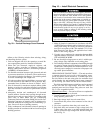
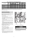
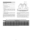
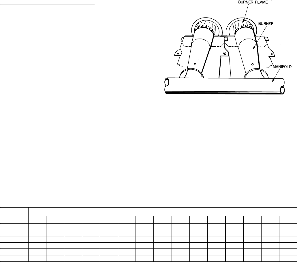
CHECK BURNER FLAME — With burner access panel re-
moved, observe the unit heating operation. Watch the burner
flames to see if they are light blue and soft in appearance,
and that the flames are approximately the same for each burner.
Propane will have blue flame with yellow tips. See Fig. 25.
Refer to Maintenance section for information on burner
removal.
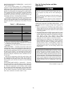
AIRFLOWAND TEMPERATURE RISE — The heating sec-
tion for each size unit is designed and approved for heating
operation within the temperature-rise range stamped on the
unit rating plate.
Table 6 shows the approved temperature-rise range for each
heating input, and the air delivery cfm at various tempera-
ture rises. The heating operation airflow must produce a tem-
perature rise that falls within the approved range.
Refer to Evaporator Airflow and Airflow Adjustments sec-
tion on page 35 to adjust heating airflow when required.
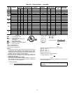
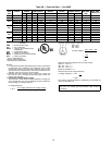
Table 6 — Air Delivery (Cfm) at Indicated Temperature Rise and Rated Heating Input
HEATING
INPUT
(Btuh)
TEMPERATURE RISE °F
20 25 30 35 40 45 50 55 60 65 70 75 80 85 90
40,000 1389 1111 926 794 694 617 556 ————————
56,000 2083 1667 1389 1190 1042 926 833 758 ———————
80,000 2778 2222 1852 1587 1389 1235 1111 1010 926 855 794 ————
95,000 3472 2778 2315 1984 1736 1543 1389 1263 1157 1068 992 926 868 — —
120,000 4167 3333 2778 2381 2083 1852 1667 1515 1389 1282 1190 1111 1042 980 926
136,000 5037 4029 3358 2878 2518 2238 2014 1831 1679 1549 1439 1343 1259 1185 1119
NOTE: Dashed areas do not fall within the approved temperature rise range of the unit.
Fig. 25 — Monoport Burners
25