


Alternate Power Entry
1. Remove knockouts in fixed compressor panel located on
duct panel side of unit.
2. Route high-voltage leads into high-voltage terminal box.
3. Connect ground wire to green-yellow wire using field-
supplied splice.
4. Connect power wires to unit high-voltage leads.
5. On 3-phase units, locate blue wire projecting from com-
pressor junction box. Cut wire at partition and route into
high-voltage junction box through grommet in back of
junction box.
6. On 3-phase units, strip back blue lead and connect to third
leg of the power wires.
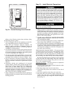
SPECIAL PROCEDURES FOR 208-V OPERATION
Make sure that the gas supply then the power supply to
the unit is switched OFF before making any wiring
changes. Electrical shock can cause personal injury or
death.
1. Disconnect the orange transformer-primary lead from the
contactor. See unit wiring label.
2. Remove the tape and wirenut from the terminal on the
end of the red transformer-primary lead.
3. Save the wirenut.
4. Connect the red lead to the contactor terminal from which
the orange lead was disconnected.
5. Using the wirenut removed from the red lead, insulate
the loose terminal on the orange lead.
6. Wrap the cover with electrical tape so that the metal ter-
minal cannot be seen.
CONTROL VOLTAGE CONNECTIONS; NON-
INTEGRATED CONTROL MOTOR (NON-ICM) UNITS
— Locate the room thermostat on an inside wall in the space
to be conditioned, where it will not be subjected to either a
cooling or heating source or direct exposure to sunlight. Mount
the thermostat 4 to 5 ft above the floor.
NOTE: Do not use any type of power-stealing thermostat.
Unit control problems may result.
Use no. 18 American Wire Gage (AWG) color-coded, in-
sulated (35 C minimum) wires to make the control voltage
connections between the thermostat and the unit. If the ther-
mostat is located more than 100 ft from the unit (as mea-
sured along the control voltage wires), use no. 16 AWG color-
coded, insulated (35 C minimum) wires.
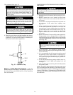
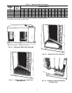
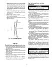
Standard Connection — Remove knockout hole located in
the flue panel adjacent to the control access panel. See
Fig. 2-9. Remove the rubber grommet from the installer’s
packet (included with unit) and install grommet in the knock-
out opening. Provide a drip loop before running wire through
panel.
Run the low-voltage leads from the thermostat, through
the inlet hole, and into unit low-voltage splice box.
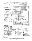
Locate five 18-gage wires leaving control box. These low-
voltage connection leads can be identified by the colors red,
green, yellow, brown, and white. (See Fig. 21.) Ensure the
leads are long enough to be routed into the low-voltage splice
box (located below right side of control box). Cut wires at
the point where they exit control box; do NOT cut yellow
wire on 48SX024,030 units. Stripped yellow wire is located
in connection box. Route leads through hole in bottom of
control box and make low-voltage connections as shown in
Fig. 21. Secure all cut wires, so that they do not interfere
with operation of unit.
Alternate Connection — Remove knockout in compressor fixed
panel located below high-voltage knockout. Remove the rub-
ber grommet from the installer’s packet (included with unit)
and install grommet in the knockout opening. Route ther-
mostat wires through grommet providing drip loop at panel.
Connect low-voltage leads as shown in Fig. 21. On 48SX024
and 030 units, the yellow wire originating from discharge
thermostat of compressor must be cut and routed into low-
voltage section of junction box.
CONTROL VOLTAGE CONNECTIONS; INTEGRATED
CONTROL MOTOR (ICM) UNITS
Routing Control Power Wires (24 v) — Remove knockout
in the compressor fixed access panel located below the high-
voltage knockout. Remove the rubber grommet from the in-
staller’s packet (included with unit) and install grommet in
the knockout opening. Route thermostat wires through grom-
met providing drip loop at panel. Connect low-voltage leads
to the thermostat.
Alternate Connection (24 v) — Remove knockout in the flue
panel adjacent to the control access panel. Remove the rub-
ber grommet from the installer’s packet (included with unit)
and install grommet in the knockout opening. Provide a drip
loop before running wire through panel. Run the low-
voltage leads from the thermostat, through the inlet hole, and
into the unit low-voltage splice box.
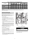
Connecting to Easy Select Interface Board — The Easy Se-
lect interface board is located in the control box area. The
Easy Select interface board is factory wired to the motor,
and factory default selections are preset.
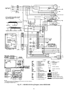
Locate the five 18-gage thermostat lead wires of plug as-
sembly 1 (PL1) attached to the Easy Select interface board
(See Fig. 22 and wiring diagrams for units 48SX048 and
060 on pages 31 and 33.) These low voltage connection leads
are identified by the colors red, green, yellow, brown, and
white. Cut the wires between the 2 wire ties approximately
4 in. from the plug. Connect low-voltage leads to the ther-
mostat. Secure all cut wires in the control and splice boxes
so they do not interfere with the proper operation of the unit.
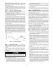
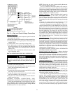
LEGEND
Field Control-Voltage Wiring
Field High-Voltage Wiring
NOTE: Use blue wire for 3-phase units only.
Fig. 21 — High- and Control-Voltage Connections
21