


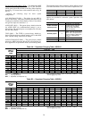
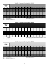
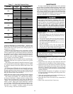
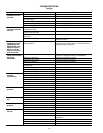


Table 17 — Wet Coil Pressure Drop
UNIT SIZE
AIRFLOW
(cfm)
PRESSURE DROP
(in. wg)
018*
600 0.069
700 0.082
800 0.102
900 0.116
024
600 0.039
700 0.058
800 0.075
900 0.088
030
900 0.088
1000 0.095
1200 0.123
036
1000 0.068
1200 0.088
1400 0.108
1600 0.123
042
1000 0.048
1200 0.069
1400 0.088
1600 0.102
048
1400 0.068
1600 0.075
1800 0.088
060
1700 0.082
1900 0.095
2100 0.108
2300 0.123
*Unit 48SS only.
COOLING SEQUENCE OF OPERATION — With the room
thermostat SYSTEM switch in the COOL position and the
FAN switch in the AUTO. position, the cooling sequence of
operation is as follows:
When the room temperature rises to a point that is slightly
above the cooling control setting of the thermostat, the ther-
mostat completes the circuit between thermostat terminal R
to terminals Y and G. These completed circuits through the
thermostat connect contactor coil (C) (through unit wire Y)
and blower relay coil (BR) (through unit wire G) across the
24-v secondary of transformer (TRAN).
NOTE: The blower relay coil (BR) is used on standard non-
ICM units, ICM units use evaporator (indoor) fan on (IFO)
connection.
The normally-open contacts of energized contactor (C) close
and complete the circuit through compressor motor (COMP)
to condenser (outdoor) fan motor (OFM). Both motors start
instantly.
On standard non-ICM units, the set of normally-open con-
tacts of energized relay BR close and complete the circuit
through evaporator blower (indoor) fan motor (IFM). On ICM
units, the IFO completes the circuit through evaporator blower
IFM. The blower motor starts instantly.
NOTE: Once the compressor has started and then has stopped,
it should not be started again until 5 minutes have elapsed.
The cooling cycle remains ‘‘on’’ until the room tempera-
ture drops to point that is slightly below the cooling control
setting of the room thermostat. At this point, the thermostat
‘‘breaks’’ the circuit between thermostat terminal R to ter-
minals Y and G. These open circuits deenergize contactor
coil C and relay coil BR. The condenser and compressor mo-
tors stop. After a 30-second delay, the blower motor stops.
The unit is in a ‘‘standby’’ condition, waiting for the next
‘‘call for cooling’’ from the room thermostat.
MAINTENANCE
To ensure continuing high performance, and to minimize
the possibility of premature equipment failure, periodic main-
tenance must be performed on this equipment. This combi-
nation heating/cooling unit should be inspected at least once
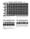
each year by a qualified service person. To troubleshoot heat-
ing or cooling of units, refer to tables at the back of the book.
NOTE TO EQUIPMENT OWNER: Consult your local dealer
about the availability of a maintenance contract.
The ability to properly perform maintenance on this equip-
ment requires certain expertise, mechanical skills, tools,
and equipment. If you do not possess these, do not at-
tempt to perform any maintenance on this equipment
other than those procedures recommended in the User’s
Manual. FAILURE TO HEED THIS WARNING
COULD RESULT IN SERIOUS PERSONAL INJURY
AND POSSIBLE DAMAGE TO THIS EQUIPMENT.
Failure to follow these warnings could result in serious
personal injury:
1. Turn off gas supply, then turn off electrical power to
the unit before performing any maintenance or serv-
ice on the unit.
2. Use extreme caution when removing panels and parts.
As with any mechanical equipment, personal injury
can result from sharp edges, etc.
3. Never place anything combustible either on, or in con-
tact with, the unit.
4. Should overheating occur, or the gas supply fail to
shut off, shut off the external main manual gas valve
to the unit, then shut off the electrical supply.
Errors made when reconnecting wires may cause im-
proper and dangerous operation. Label all wires prior to
disconnection when servicing.
The minimum maintenance requirements for this equip-
ment are as follows:
1. Inspect air filter(s) each month. Clean or replace when
necessary.
2. Inspect indoor coil, drain pan, and condensate drain each
cooling season for cleanliness. Clean when necessary.
3. Inspect blower motor and wheel for cleanliness and check
lubrication each heating and cooling season. Clean and
lubricate (if required) when necessary. For first heating
season, inspect blower wheel bimonthly to determine proper
cleaning frequency.
4. Check electrical connections for tightness and controls
for proper operation each heating and cooling season. Serv-
ice when necessary.
5. Check and inspect heating section before each heating sea-
son. Clean and adjust when necessary.
6. Check flue hood screen and remove any obstructions if
necessary.
7. Check vent screen and clean if necessary.
44