


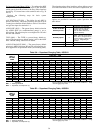
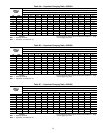
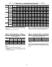
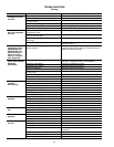

Table 14 — Dry-Coil Air Delivery* — Downflow Discharge at 230 and 460 V — Unit 48SX
(Deduct 10% from Cfm and Watts for 208 V Operation)
UNIT
48SX
MOTOR
SPEED
AIR
DELIVERY
EXTERNAL STATIC PRESSURE (in. wg)
0.0 0.1 0.2 0.3 0.4 0.5 0.6 0.7 0.8 0.9 1.0
024,
030
Low
Watts 280 275 265 255 250 245 240 ††††
Cfm 820810755700660600560††††
Med
Watts 365 360 350 345 340 330 320 310 300 † †
Cfm 1025 1010 975 940 900 850 800 720 630 † †
High
Watts † † 490 480 470 460 445 430 410 390 380
Cfm † † 1300 1255 1200 1150 1080 1005 915 790 620
036
Low
Watts 520 495 474 458 445 425 †††††
Cfm 1375 1335 1290 1240 1200 1140 †††††
Med
Watts 575 560 535 510 480 460 440 425 † † †
Cfm 1520 1490 1450 1400 1380 1300 1200 1080 † † †
High
Watts ††††650614575540510480†
Cfm ††††1560 1500 1380 1280 1170 1060 †
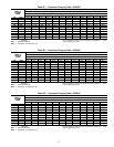
042
Low
Watts 490 480 470 460 450 430 410 390 † † †
Cfm 1400 1380 1340 1300 1250 1200 1140 1070 † † †
Med
Watts 590 580 560 545 525 505 480 450 420 † †
Cfm 1600 1560 1540 1470 1430 1360 1300 1220 1120 † †
High
Watts †††††700670640600560500
Cfm †††††1780 1670 1600 1480 1340 1100
048**
Low
Watts 1050 1000 970 930 870 810 750 680 600 † †
Cfm 1850 1830 1800 1785 1750 1700 1640 1500 1330 † †
High
Watts † † † 1050 1000 930 870 810 740 665 †
Cfm † † † 2000 1940 1850 1750 1635 1500 1300 †
*Air delivery values are without air filter and are for dry coil. See Table 17
for wet coil pressure drop. Deduct field-supplied air filter pressure drop
and wet coil pressure drop to obtain external static pressure available
for ducting.
†Unit air delivery is outside of operating range.
**For 460 v units only.
NOTE: Do not operate the unit at a cooling airflow that is less than
350 cfm for each 12,000 Btuh of rated cooling capacity. Evaporator-coil
icing may occur at airflows below this point. Water blow-off may occur at
airflows above 450 cfm per 12,000 Btuh of rated cooling capacity.
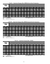
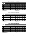
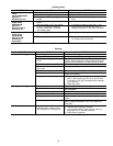
Table 15 — Dry Coil Air Delivery* — Heating —
Horizontal and Downflow Discharge for Integrated
Control Motor Units at 230-V (Deduct 10% from Cfm
for 208-V Operation)
HEATING
INPUT
(Btuh)
EASY SELECT BOARD TERMINALS (Cfm)
1234
80,000 1300 1400 1600 1750
100,000 — 1400 1600 1750
95,000 — — 1600 1750
136,000 — — — 1750
*Air delivery values are for dry coil at 230 v. Airflow is independent of
external static pressure within Ϯ5% of table values up to
0.8 in wg.
NOTES:
1. Dashed areas do not fall within approved range.
2. The above values occur with the AC/HPCFMADJUST select jumper
set on MED.
3. Airflow can be adjusted ϩ10% or −10% by selecting HI or LO for
all modes except FAN ONLY.
Table 16 — Dry-Coil Air Delivery* — Fan Only and
Cooling — Horizontal and Downflow Discharge for
Integrated Control Motor Units at 230-V (Deduct 10%
from Cfm for 208-V Operation)
UNIT 48SX FAN ONLY (Cfm) COOLING (Cfm)
048 1400 1600
060 1750 2000
*Air delivery values are for dry coil at 230 v. Airflow is independent of
external static pressure within Ϯ5% of table values up to
0.8 in wg.
NOTE: Do not operate the unit at a cooling airflow that is less than
350 cfm for each 12,000 Btuh of rated cooling capacity. Evaporator-
coil icing may occur at airflows below this point. Water blow-off may
occur at airflows above 450 cfm per 12,000 Btuh of rated cooling
capacity.
43