


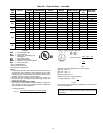
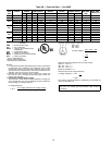

Table 5 — Rated Gas Inputs at Indicated Manifold Pressures
UNIT 48SS,SX
NUMBER
OF
ORIFICES
GAS SUPPLY PRESSURE
(in. wg)
MANIFOLD
PRESSURE
(in. wg)
NATURAL GAS PROPANE*
Natural Propane
Orifice
Drill
Size
Heating
Input
(Btuh)†
Orifice
Drill
Size
Heating
Input
(Btuh)†
Min Max Min Max Natural Propane
018040, 024040, 030040 1 4.0 13.0 4.0 13.0 3.5 3.1 32 40,000 41 40,000
024060, 030060, 036060, 042060 2 4.0 13.0 4.0 13.0 3.5 3.3 40 56,000 47 54,000
030080, 036080, 042080,
048080, 060080
2 4.0 13.0 4.0 13.0 3.5 3.4 32 80,000 42 80,000
036100, 042100, 048100, 060100 2 4.0 13.0 4.0 13.0 3.5 3.7 30 95,000 40 95,000
036120, 042120, 048120, 060120 3 4.0 13.0 4.0 13.0 3.5 3.5 32 120,000 42 115,000
048140, 060140 3 4.0 13.0 4.0 13.0 3.5 3.4 31 136,000 40 133,000
*When a unit is converted to propane, different size orifices must be used. See separate natural-to-propane conversion kit
instructions.
†Based on altitudes from sea level to 2000 ft above sea level. For altitudes above 2000 ft: reduce input rating 4% for each
additional 1000 ft above 2000 ft. In Canada, from 2000 ft above sea level to 4500 ft above sea level, derate the unit 10%.
NOTE: Unit size 018 is 48SS only.
Measure Gas Flow (Natural Gas Units) — Minor adjust-
ment to the gas flow can be made by changing the man-
ifold pressure. The manifold pressure must be maintained
between 3.4 and 3.6 in. wg. If larger adjustments are re-
quired, change main burner orifices following the recom-
mendations of national and local codes.
NOTE: All other appliances that use the same meter must be
turned off when gas flow is measured at the meter.
Proceed as follows:
1. Turn off gas supply to unit.
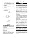
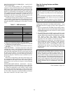
2. Remove pipe plug on manifold (see Fig. 24), then con-
nect manometer at this point. Turn on gas to unit.
3. Record number of seconds for gas meter test dial to make
one revolution.
4. Divide number of seconds in Step 3 into 3600 (number
of seconds in one hour).
5. Multiply result of Step 4 by the number of cu ft shown
for one revolution of test dial to obtain cu ft of gas flow
per hour.
6. Multiply result of Step 5 by Btu heating value of gas to
obtain total measured input in Btuh. Compare this value
with heating input shown in Table 5. (Consult the local
gas supplier if the heating value of gas is not known.)
EXAMPLE: Assume that the size of test dial is 1 cu ft, one
revolution takes 30 seconds, and the heating value of the gas
is 1050 Btu/ft
3
. Proceed as follows:
1. 30 seconds to complete one revolution.
2. 3600 ÷ 30 = 120.
3.120x1=120ft
3
of gas flow/hr.
4. 120 x 1050 = 126,000 Btuh input.
If the desired gas input is 120,000 Btuh, only a minor change
in the manifold pressure is required.
Observe manifold pressure and proceed as follows to ad-
just gas input:
1. Remove cover screw over regulator adjustment screw on
gas valve.
2. Turn regulator adjustment screw clockwise to increase gas
input, or turn regulator adjustment screw counterclock-
wise to decrease input. Manifold pressure must be be-
tween 3.4 and 3.6 in. wg.
Unsafe operation of the unit may result if manifold
pressure is outside this range. Personal injury or unit
damage may result.
3. Replace cover screw cap on gas valve.
4. Turn off gas supply to unit. Remove manometer from pres-
sure tap and replace pipe plug on gas valve. Turn on gas
to unit and check for leaks.
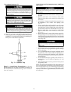
MANIFOLD PIPE PLUG
Fig. 24 — Burner Assembly
24