


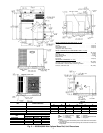
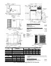
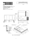
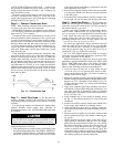
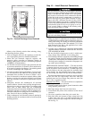

UNITS WITH OPTIONAL BASE RAIL — Lifting holes
are provided in optional base rail as shown in Fig. 13. Op-
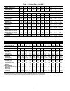
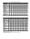
erating weights are shown in Tables 1 and 2. Refer to rig-
ging instructions on unit.
Protective wood support must be removed from unit be-
fore unit is mounted to curb. Remove 4 screws that secure
support above rigging holes in rails. Slide support out through
rectangular hole in rail. See Fig. 13.
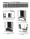
Step 6 — Connect Condensate Drain
NOTE: When installing condensate drain connection be sure
to comply with local codes and restrictions.
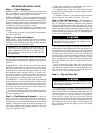
Model 48SS,SX disposes of condensate water through a
3
⁄
4
in. NPT fitting which exits through the compressor access
panel. See Fig. 2-9 for location.
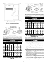
Condensate water can be drained directly onto the roof in
rooftop installations (where permitted) or onto a gravel apron
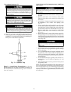
in ground-level installations. Install a field-supplied conden-
sate trap at end of condensate connection to ensure proper
drainage. Make sure that the outlet of the trap is at least
1 in. lower than the drain-pan condensate connection to pre-
vent the pan from overflowing. See Fig. 14. Prime the trap
with water. When using a gravel apron, make sure it slopes
away from the unit.
If the installation requires draining the condensate water
away from the unit, install a 2-in. trap at the condensate con-
nection to ensure proper drainage. See Fig. 14. Make sure
that the outlet of the trap is at least 1 in. lower than the drain-
pan condensate connection to prevent the pan from over-
flowing. Prime the trap with water. Connect a drain tube us-
ing a minimum of
3
⁄
4
-in. PVC or
3
⁄
4
-in. copper pipe (all field-
supplied) at the outlet end of the 2-in. trap. Do not undersize
the tube. Pitch the drain tube downward at a slope of at least
one in. for every 10 ft of horizontal run. Be sure to check the
drain tube for leaks.
Step 7 — Install Flue Hood — The flue hood as-
sembly is shipped screwed to the control box in the burner
compartment. Remove the burner access panel to locate the
assembly.
For units being installed in California Air Quality Man-
agement Districts which require NO
x
emissions of
40 nanograms/joule or less, kit CRLOWNOX001A00 must
be installed.
The venting system is designed to ensure proper vent-
ing. The flue hood assembly must be installed as indi-
cated in this section of the unit installation instructions.
Install the flue hood as follows:
1. This installation must conform with local building codes
and with the National Fuel Gas Code (NFGC),ANSI Z223.1
(in Canada, CAN/CGAB149.1, and B149.2) or NFPA(Na-
tional Fire Protection Association) latest revision. Refer
to Provincial and local plumbing or wastewater codes and
other applicable local codes.
2. Remove from shipping location. Place vent cap assembly
over flue panel. Orient screw holes in vent cap with holes
in the flue panel.
3. Secure flue hood to flue panel by inserting a single screw
on the right side, the left side, and the top of the hood.
Step 8 — Install Gas Piping — The gas supply pipe
enters the unit through the access hole provided. The gas
connection to the unit is made to the
1
⁄
2
-in. FPT gas inlet on
the manual shutoff or gas valve.
Install a gas supply line that runs to the heating section.
Refer to Table 3 and the NFGC for gas pipe sizing. Do not
use cast-iron pipe. It is recommended that a black iron pipe
is used. Check the local utility for recommendations con-
cerning existing lines. Size gas supply piping for 0.5 in. wg
maximum pressure drop. Never use pipe smaller than the
1
⁄
2
-in. FPT gas inlet on the unit gas valve.
For natural gas applications, the gas pressure at unit gas
connection must not be less than 4.0 in. wg or greater than
13 in. wg while the unit is operating. For propane applica-
tions, the gas pressure must not be less than 4.0 in. wg or
greater than 13 in. wg at the unit connection.
An
1
⁄
8
-in. NPT plugged tapping accessible for test gage
connection must be installed immediately upstream of the
gas supply connection to the furnace.
When installing the gas supply line, observe local codes
pertaining to gas pipe installations. Refer to the NFGC ANSI
Z223.1-1988 NFPA latest edition (in Canada, CAN/CGA
B149.1, (2)-M86). In the absence of local building codes,
adhere to the following pertinent recommendations:
1. Avoid low spots in long runs of pipe. Grade all pipe
1
⁄
4
inch in every 15 ft to prevent traps. Grade all hori-
zontal runs downward to risers. Use risers to connect to
heating section and to meter.
2. Protect all segments of piping system against physical and
thermal damage. Support all piping with appropriate straps,
hangers, etc. Use a minimum of one hanger every 6 ft.
For pipe sizes larger than
1
⁄
2
in., follow recommendations
of national codes.
3. Apply joint compound (pipe dope) sparingly and only to
male threads of joint when making pipe connections. Use
only pipe dope that is resistant to action of liquefied
petroleum gases as specified by local and/or national codes.
Never use Teflon tape.
4. Install sediment trap in riser leading to heating section
per Fig. 15. This drip leg functions as a trap for dirt and
condensate.
5. Install an accessible, external, manual main shutoff valve
in gas supply pipe within 6 ft of heating section.
6. Install ground-joint union close to heating section be-
tween unit manual shutoff and external manual main shut-
off valve.
7. Pressure-test all gas piping in accordance with local and
national plumbing and gas codes before connecting pip-
ing to unit.
NOTE: Pressure test the gas supply system after the gas
supply piping is connected to the gas valve. The supply
piping must be disconnected from the gas valve during
the testing of the piping systems when test pressure is in
excess of 0.5 psig. Pressure test the gas supply piping
system at pressures equal to or less than 0.5 psig. The
unit heating section must be isolated from the gas piping
system by closing the external main manual shutoff valve
and slightly opening the ground-joint union.
Fig. 14 — Condensate Trap
13