


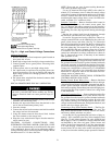
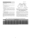
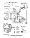
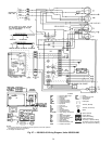
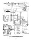
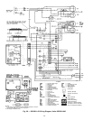
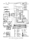
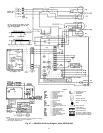
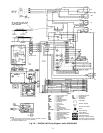

HEATING SEQUENCE OF OPERATION — See Fig. 26-33
and unit wiring label.
On a call for heating, terminal ‘‘W’’ of the thermostat is
energized, starting the induced-draft motor. When the hall-
effect sensor on the induced-draft motor senses that it has
reached the required speed, the burner sequence begins. This
function is performed by the integrated gas control (IGC).
The evaporator-fan motor is energized 45 seconds after flame
is established. When the thermostat is satisfied and ‘‘W’’ is
deenergized, the burners stop firing and the evaporator-fan
motor shuts off after a 45-second time-off delay.
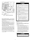
A LED (light-emitting diode) indicator is provided on the
control board to monitor operation. The control board is lo-
cated by removing the burner access panel. During normal
operation, the LED is continuously on. See Table 7 for error
codes.
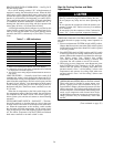
Table 7 — LED Indications
ERROR CODE LED INDICATION
Normal Operation On
Hardware Failure Off
Fan On/Off Delay Modified 1 Flash
Limit Switch Fault 2 Flashes
Flame Sense Fault 3 Flashes
Four Consecutive Limit Switch Faults 4 Flashes
Ignition Lockout Fault 5 Flashes
Induced-Draft Motor Fault 6 Flashes
Rollout Switch Fault 7 Flashes
Internal Control Fault 8 Flashes
NOTES:
1. There is a 3-second pause between error code displays.
2. If more than one error code exists, all applicable error codes will
be displayed in numerical sequence.
3. This chart is on the wiring diagram located inside the burner ac-
cess panel.
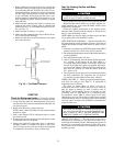
LIMIT SWITCHES — Normally-closed limit switch (LS)
completes the control circuit through the thermostat R cir-
cuit. Should the leaving-air temperature rise above the maxi-
mum allowable temperature, the limit switch opens and the
R control circuit ‘‘breaks.’’Any interruption in the R control
circuit instantly closes the gas valve and stops gas flow to
the burners and pilot. The blower motor continues to run un-
til LS resets.
When the air temperature at the limit switch drops to the
low-temperature setting of the limit switch, the switch closes
and completes the R control circuit. The electric-spark ig-
nition system cycles and the unit returns to normal heating
operation.
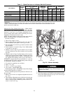
AUXILIARY LIMIT SWITCH — ROLLOUT — The func-
tion of the switch is to close the main gas valve in the event
of flame rollout. The switch is located above the main burn-
ers. When the temperature at the auxiliary switch reaches
the maximum allowable temperature, the R control circuit
trips, closing the gas valve and stopping gas flow to the burn-
ers. The indoor (evaporator) fan motor (IFM) and induced
draft motor continue to run until switch is reset.
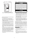
Start Up Cooling Section and Make
Adjustments
Complete the required procedures given in the Pre-
Start-Up section on page 22 before starting the unit.
Do not jumper any safety devices when operating the
unit.
Do not operate the compressor when the outdoor tem-
perature is below 40 F (unless accessory low-ambient
kit is installed).
Do not rapid-cycle the compressor. Allow 5 minutes be-
tween ‘‘on’’ cycles to prevent compressor damage.
CHECKING COOLING CONTROL OPERATION — Start
and check the unit for proper cooling control operation as
follows:
1. Place room thermostat SYSTEM switch in OFF position.
Observe that blower motor starts when FAN switch is placed
in ON position and shuts down when FAN switch is placed
in AUTO. position.
2. Place SYSTEM switch in COOL position and FAN switch
in AUTO. position. Set cooling control below room tem-
perature. Observe that compressor, condenser fan, and evapo-
rator blower motors start. Observe that cooling
cycle shuts down when control setting is satisfied. The
evaporator fan will continue to run for 30 seconds.
3. When using an auto.-changeover room thermostat, place
both SYSTEM and FAN switches in AUTO. positions.
Observe that unit operates in heating mode when tem-
perature control is set to ‘‘call for heating’’ (above room
temperature) and operates in cooling mode when tem-
perature control is set to ‘‘call for cooling’’ (below room
temperature).
IMPORTANT: Three-phase, scroll compressor units
(48SS048,060 and 48SX036-060) are direction-oriented.
These units must be checked to ensure proper com-
pressor 3-phase power lead orientation. If not cor-
rected within 5 minutes, the internal protector will shut
off the compressor. The 3-phase power leads to the unit
must be reversed to correct rotation. When turning back-
wards, scroll compressors emit elevated noise levels,
and the difference between compressor suction and dis-
charge pressures may be dramatically lower than
normal.
(Text continued on page 35.)
26