


8
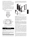
PositioningonCurb—
For full perimeter curbs CRRFCURB072A00 and
073A00, the clearance between the roof curb and the front
and rear base rails should be
1
/
4
in (6.4 mm). The
clearance between the curb and the end base rails should
be
1
/
2
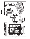
in (13 mm). For retrofit applications with curbs
CRRFCURB003A01 and 4A01, the unit should be
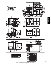
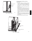
position as shown in Fig. 6. Maintain the 15.5 in (394
mm) and 8
5
/
8
in (220 mm) clearances and allow the
22
5
/
16
in (567 mm) dimension to float if necessary.
C10003
Fig. 6 -- Retrofit Installation Dimensions
If the alternative condensate drain location through the
bottom of the unit is used in conjunction with a retrofit
curb, the hole in the curb must be moved 12.5 in (320
mm) towards the end of the unit.
Although unit is weatherproof, guard against water from
higher level runoff and overhangs.
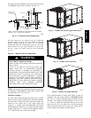
Remove all shipping materials and top skid. Remove extra
center post from the condenser end of the unit so that the
condenser end of the unit matches Fig. 16 -- 18. Recycle
or dispose of all shipping materials.
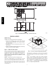
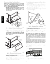
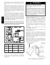
Step 7 — Convert to Horizontal and Connect
Ductwork (when required)
Unit is shipped in the vertical duct configuration. Unit
without factory--installed economizer or return air smoke
detector option may be field--converted to horizontal
ducted configuration using accessory
CRDUCTCV001A00. To convert to horizontal
configuration, remove screws from side duct opening
covers and remove covers.
Discard the supply duct cover. Install accessory
CRDUCTCV001A00 to cover the vertical supply duct
opening. Use the return duct cover removed from the end
panel to cover the vertical return duct opening.
Field--supplied flanges should be attached to horizontal
duct openings and all ductwork should be secured to the
flanges. Insulate and weatherproof all external ductwork,
joints, and roof or building openings with counter flashing
and mastic in accordance with applicable codes.
Do not cover or obscure visibility to the unit’s informative
data plate when insulating horizontal ductwork.
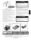
C06108
Fig. 7 -- Horizontal Conversion Panels
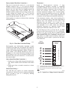
Step 8 — Install Outside Air Hood
Economizer Hood Removal and Setup --
Factory Option —
1. The hood is shipped in knock--down form and located
in the return air compartment. It is attached to the
economizer using two plastic tie--wraps.
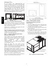
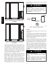
2. To gain access to the hood, remove the filter access
panel. (See Fig. 8.)
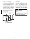
3. Locate and cut the (2) plastic tie--wraps, being careful
to not damage any wiring. (See Fig. 9.)
4. Carefully lift the hood assembly through the filter
access opening and assemble per the steps outlined in
Economizer Hood and Two–Position Hood on page 10.
FILTER ACCESS PANEL
INDOOR COIL ACCESS PANEL
C10004
Fig. 8 -- Typical Access Panel Locations
548J*14D