


17
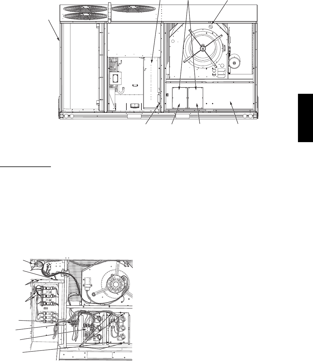
HEATER
MOUNTING
BRACKET
HEATER
MODULE
(LOCATION 2)
HEATER
MODULE
(LOCATION 1)
SINGLE POINT
BOX
MOUNTING
SCREW
SINGLE
POINT BOX
HEATER
COVERS
MANUAL RESET
LIMIT SWITCH
DISCONNECT
MOUNTING
LOCATION
C10029
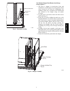
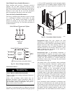
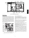
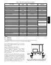
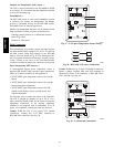
Fig. 29 -- Typical Component Location
Single Point Boxes
When heaters are installed, power wiring to both heaters
and the rest of the unit is connected via the single point
box accessory, which will be installed directly under the
unit control box, just to the left of the partition separating
the indoor section (with electric heaters) from the outdoor
section. The single point box has a hinged access cover.
See Fig. 29. The single point box also includes pigtails to
complete the wiring between the single point box and the
unit’s main control box terminals. Refer to the accessory
heater and Single Point Box installation instructions for
details on tap connections.
A
L
LIE
D
P
A
M
O
DE
L
N
O
.
ERI
A
L
N
O.
C
O
R
P
.
11
13
21
23
O
D
2
2
.
2
3
1
2
3
ISTED
AIR
NDITIONING
UIP
ACCESS
346N
.
P
/ N
2-
5
6
10
-
4
REV
1
1
13
2
1
2
3
CONTROL
BOX
BUSHING
SINGLE
POINT BOX
MOUNTING
SCREWS
FOAM
BUSHING
DRIP BOOT
BRACKET
MOUNTING
SCREWS
HEATER
RELAYS
POWER
WIRES
HEATER
MOUNTING
SCREWS
C08136
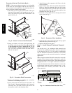
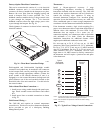
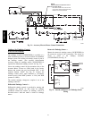
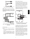
Fig. 30 -- Typical Single Point Installation
Heater and Supplementary Fuses —
When the unit MOCP device value exceeds 60--A,
unit--mounted supplementary fuses are required for each
heater circuit. These fuses are included in accessory
Single Point Boxes, with power distribution and fuse
blocks.
All fuses on 548J units are 60--A. (Note that all heaters are
qualified for use with a 60--A fuse, regardless of actual
heater ampacity, so only 60--A fuses are necessary.)
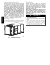
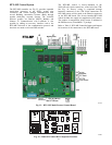
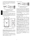
Heater Low--Voltage Control Connections —
One or two heaters can be installed in the unit. Use the
wiring procedure listed below for each heater as
determined by the number of stages in the heater.
Single Stage Heaters: Single--stage heaters will have an
orange and a brown control wire. Connect these to the
orange and brown wires located on TB4.
Two Stage Heaters: Two--stage heaters will have orange,
purple, red and brown wires. The orange and the purple
are the control wires and the red and brown wires feed the
safety circuit. Connect both the orange and the purple
wires to the orange wire locations of TB4. Connect the
red and brown wires to red and brown wires on TB4. If
more than one heater is installed, repeat the wiring
procedure for the second heater. The 3 locations across
the top of TB4 do allow a switch to be installed in series
with some of the heaters in order to add additional heater
control.
548J*14D