


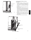
12
C10014
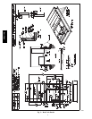
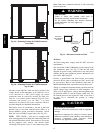
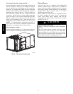
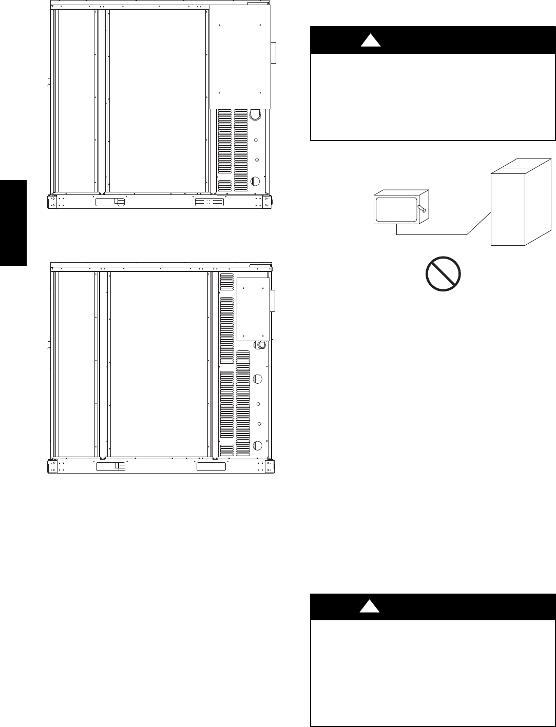
Fig. 19 -- Mounting Position for Field Disconnects
(over 100A)
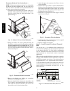
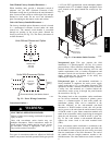
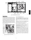
C10013
Fig. 20 -- Mounting Position for Field Disconnects
(up to 100A)
All units except 208/230-v units are factory wired for the
voltage shown on the nameplate. If the 208/230-v unit is
to be connected to a 208-v power supply, the control
transformer must be rewired by moving the black wire
with the
1
/
4
-in. female spade connector from the 230--v
connection and moving it to the 200-v
1
/
4
-in. male
terminal on the primary side of the transformer. Refer to
unit label diagram for additional information.
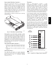
Field power wires are connected to the unit at line--side
pressure lugs at the main terminal block (TB1) or at
factory--installed option non--fused disconnect switch.
Max wire size is #2 AWG (copper only). (See Fig. 22)
NOTE: TEST LEADS -- Unit may be equipped with
short leads (pigtails) on the field line connection points off
the optional disconnect switch. These leads are for factory
run--test purposes only; remove and discard before
connecting field power wires to unit connection points.
Make field power connections directly to line connection
pressure lugs only.
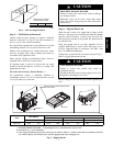
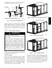
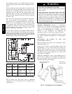
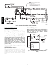
FIRE HAZARD
Failure to follow this warning could result in
intermittent operation or performance satisfaction.
Do not connect aluminum wire between disconnect
switch and furnace. Use only copper wire.
(See Fig. 21.)
!
WARNING
COPPER
WIRE ONLY
ELECTRIC
DISCONNECT
SWITCH
ALUMINUM
WIRE
A93033
Fig. 21 -- Disconnect Switch and Unit
All Units --
All field wiring must comply with the NEC and local
requirements.
Size wire based on MCA (Minimum Circuit Amps) on the
unit informative plate. See Fig. 22 and the unit label
diagram for power wiring connections to the unit power
terminal blocks and equipment ground. Maximum wire
size is #2/0 AWG per pole.
Provide a ground--fault and short--circuit over--current
protection device (fuse or breaker) per NEC Article 440
(or local codes). Refer to unit informative data plate for
MOCP (Maximum Over--current Protection) device size.
Voltage to compressor terminals during operation must be
within voltage range indicated on unit nameplate. See
Table 4. On 3--phase units, voltages between phases must
be balanced within 2% and the current within 10%. Use
the formula shown in the legend for Table 4 (see Note 2
on page 32) to determine the percent of voltage
imbalance.
UNIT DAMAGE HAZARD
Failure to follow this caution may result in equipment
damage.
Operation on improper line voltage or excessive phase
imbalance constitutes abuse and may cause damage to
electrical components. Such operation would
invalidate any applicable Bryant warranty.
CAUTION
!
548J*14D