


16
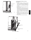
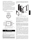
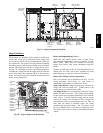
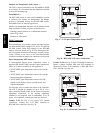
Unit without Thru--Base Connection Kit —
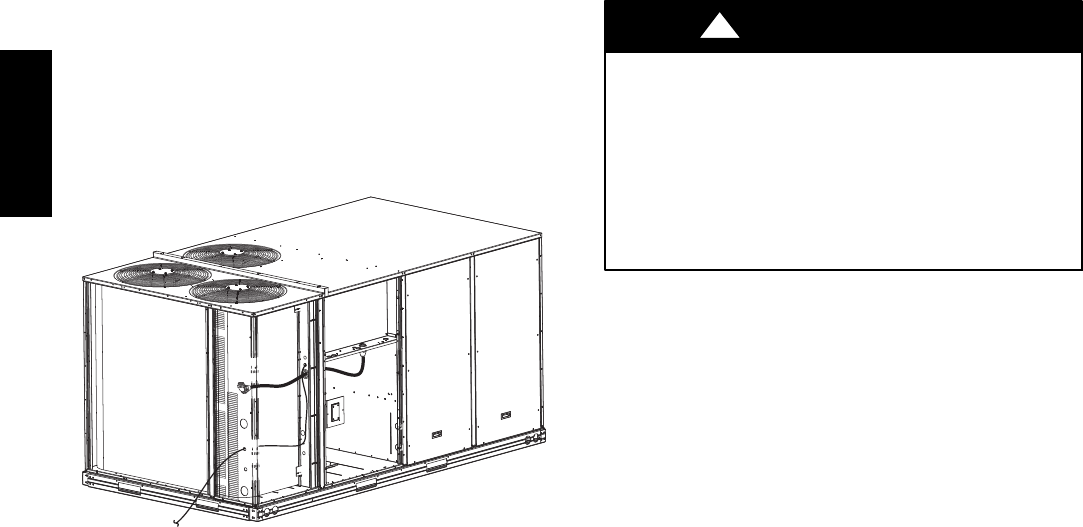
Pass the thermostat control wires through the bushing on
the unit end panel. Route the wire through the snap--in
wire tie and up to the web bushing near the control box.
Route the wire through the bushing and into the bottom
left side of the control box after removing one of the two
knockouts in the corner of the box. Using a connector at
the control box to protect the wire as it passes into the
control box. Pull the wires over to the terminal strip at the
upper left corner of the Central Terminal Board (CTB).
Use the connector at the control box and the wire tie to
ensure that the thermostat wire is tight and will not be
damaged by contact with the condenser coil. See Fig. 28.
NOTE: If thru--the--bottom connections accessory is
used, refer to the accessory installation instructions for
information on routing power and control wiring.
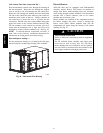
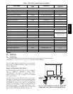
Heat Anticipator Settings —
Set heat anticipator settings at 0.14 amp for the first stage
and 0.14 amp for second--stage heating, when available.
C10018
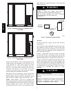
Fig. 28 -- Thermostat Wire Routing
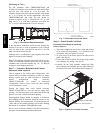
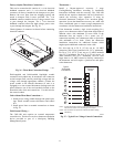
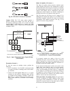
Electric Heaters
548J*14D units may be equipped with field--installed
accessory electric heaters. The heaters are modular in
design, with heater frames holding open coil resistance
wires strung through ceramic insulators, line--break limit
switches and a control contactor. One or two heater
modules may be used in a unit.
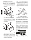
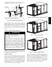
Heater modules are installed in the compartment below
the indoor (supply) fan outlet. Access is through the
indoor access panel. Heater modules slide into the
compartment on tracks along the bottom of the heater
opening. See Fig. 29.
UNIT DAMAGE HAZARD
Failure to follow this caution may result in equipment
damage.
Not all available heater modules and single point
boxes may be used in every unit. Use only those
heater modules that are UL listed for use in a specific
size unit. Refer to the label on the unit cabinet for the
list of approved heaters and single point boxes.
CAUTION
!
548J*14D