


7
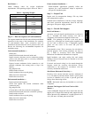
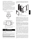
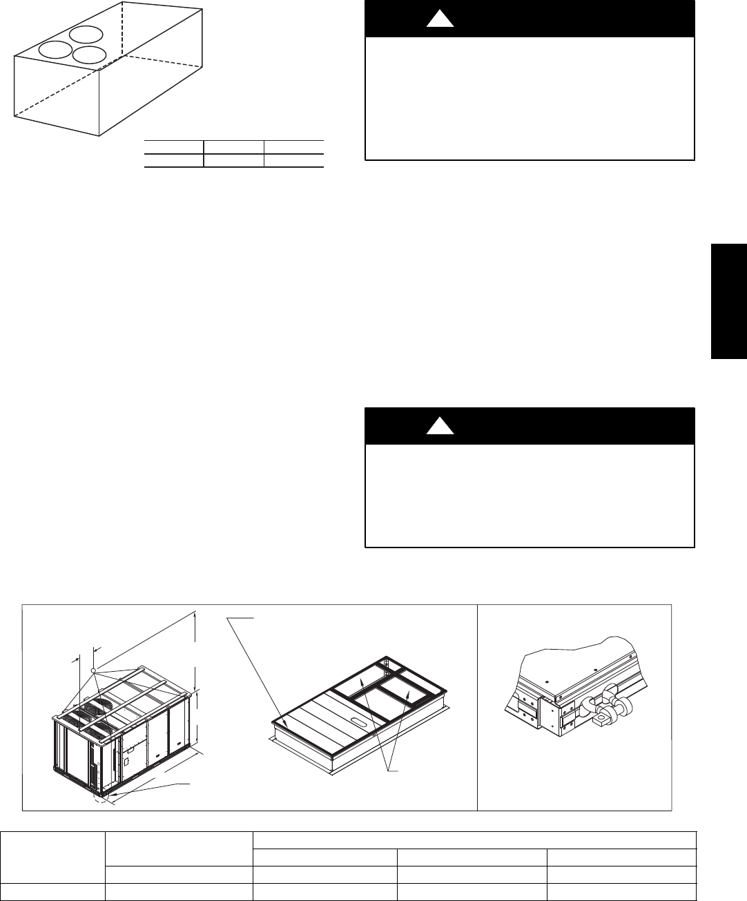
A-B
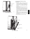
0.5” (13)
B-C
1.0” (25)
A-C
1.0” (25)
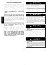
MAXIMUM ALLOWABLE
DIFFERENCE IN. (MM)
A
B
C
C10001
Fig. 4 -- Unit Leveling Tolerances
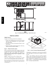
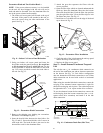
Step 5 — Field Fabricate Ductwork
Cabinet return-air static pressure (a negative condition)
shall not exceed 0.35 in. wg (87 Pa) with economizer or
0.45 in. wg (112 Pa) without economizer.
For vertical ducted applications, secure all ducts to roof curb
and building structure. Do not connect ductwork to unit.
Insulate and weatherproof all external ductwork, joints,
and roof openings with counter flashing and mastic in
accordance with applicable codes.
Ducts passing through unconditioned spaces must be
insulated and covered with a vapor barrier.
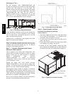
If a plenum return is used on a vertical unit, the return
should be ducted through the roof deck to comply with
applicable fire codes.
For Units with Accessory Electric Heaters —
All installations require a minimum clearance to
combustible surfaces of 1--in (25 mm) from duct for first
12--in (305 mm) away from unit.
PROPERTY DAMAGE HAZARD
Failure to follow this caution may result in damage
to roofing materials.
Membrane roofs can be cut by sharp sheet metal
edges. Be careful when placing any sheet metal parts
on such roof.
CAUTION
!
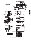
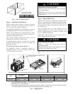
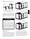
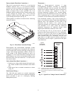
Step 6 — Rig and Place Unit
When the unit is ready to be rigged and no longer will be
lifted by a fork truck, the wood protector under the basepan
must be removed. Remove 4 screws from each base rail.
Wood protector will drop to the ground. See instructions on
the unit base rails.
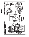
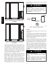
Keep unit upright and do not drop. Spreader bars are
required. Rollers may be used to move unit across a roof.
Level by using unit frame as a reference. See Table 1 and
Fig. 5 for additional information.
Lifting holes are provided in base rails as shown in Fig. 5.
Refer to rigging instructions on unit.
UNIT DAMAGE HAZARD
Failure to follow this caution may result in
equipment damage.
All panels must be in place when rigging. Unit is not
designed for handling by fork truck.
CAUTION
!
Before setting the unit onto the curb, recheck gasketing on
curb.
DETAIL “A”
SEE DETAIL “A”
914 - 1371
( 36” - 54” )
“B”
“A”
“C”
PLACE ALL GASKET IN PLACE BEFORE PLACING
UNIT ON ROOF CURB.
DUCT END
C10281
UNIT
MAX WEIGHT
DIMENSIONS
A B C
LB KG IN MM IN MM IN MM
548J*14D 2015 916 116.0 2945 55.5 1410 59.5 1510
NOTES:
1. SPREADER BARS REQUIRED — Top damage will occur if spreader bars are not used.
2. Dimensions in ( ) a re in millimeters.
3. Hook rigging sha ckles th ro ugh holes in base rail, as shown in detail “A.” Holes in base rails are centered around the
unit center of gravity. Use wooden top to pre vent rigging s traps fro m damaging unit.
Fig. 5 -- Rigging Details
548J*14D