


13
Units Without Factory--Installed Disconnect —
When installing units, provide a disconnect switch of
adequate size per NEC (National Electrical Code).
Disconnect sizing data is provided on the unit informative
plate. Locate on unit cabinet or within sight of the unit per
national or local codes. Do not cover unit informative
plate if mounting the disconnect on the unit cabinet.
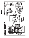
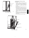
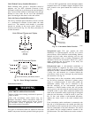
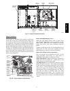
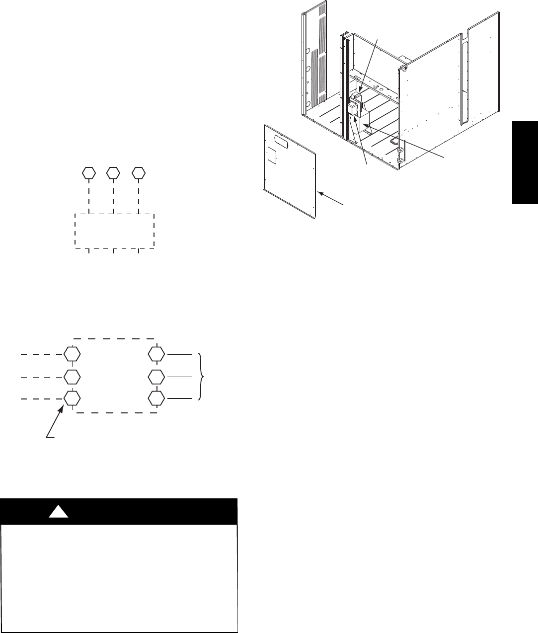
Units with Factory--Installed Disconnect —
The factory--installed option disconnect switch is located
in a weatherproof enclosure located under the main
control box. The manual switch handle is accessible
through an opening in the access panel. Discard the
factory test leads (see Fig. 22). The factory disconnect is
an 80A disconnect.
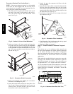
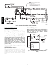
Units Without Disconnect Option
Units With Disconnect Option
2
4
6
1
3
5
L1
L2
L3
Optional
Disconnect
Switch
Disconnect factory test leads; discard.
Factory
Wiring
11 13 13
L1
L2 L3
TB1
208/230-3-60
460-3-60
575-3-60
Disconnect
per
NEC
C10015
Fig. 22 -- Power Wiring Connections
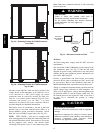
Convenience Outlets —
ELECTRICAL OPERATION HAZARD
Failure to follow this warning could result in personal
injury or death.
Units with convenience outlet circuits may use
multiple disconnects. Check convenience outlet for
power status before opening unit for service. Locate
its disconnect switch, if appropriate, and open it.
Tag--out this switch, if necessary.
!
WARNING
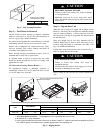
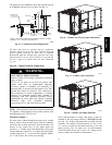
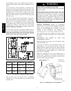
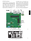
Two types of convenience outlets are offered on 548J*14D
models: non--powered and unit--powered. Both types provide
a 125--volt GFCI (ground--fault circuit--interrupter) duplex
receptacle rated at 15--A behind a hinged waterproof access
cover, located on the panel beneath the control box. See
Fig. 23.
Convenience
Outlet
GFCI
Pwd-CO
Fuse
Switch
Pwd-CO
Transformer
Disconnect
Access Panel
C10361
Fig. 23 -- Convenience Outlet Location
Non--powered type: This type requires the field
installation of a general--purpose 125--volt 15--A circuit
powered from a source elsewhere in the building. Observe
national and local codes when selecting wire size and
conduit requirements, fuse or breaker requirements and
disconnect switch size and location. Route 125--v power
supply conductors into the bottom of the utility box
containing the duplex receptacle.
Unit--powered type: A unit--mounted transformer is
factory--installed to stepdown the main power supply
voltage to the unit to 115--v at the duplex receptacle. This
option also includes a manual switch with fuse, located in
a utility box and mounted on a bracket behind the
convenience outlet; access is through the panel beneath
the control box. See Fig. 23.
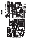
The primary leads to the convenience outlet transformer
are not factory--connected. Selection of primary power
source is a customer--option. If local codes permit, the
transformer primary leads can be connected at the
line--side terminals on the unit--mounted non--fused
disconnect or HACR breaker switch; this will provide
service power to the unit when the unit disconnect switch
or HACR switch is open. Other connection methods will
result in the convenience outlet circuit being de--energized
when the unit disconnect or HACR switch is open. See
Fig. 24. On a unit without a unit--mounted disconnect,
connect the source leads to the main terminal block
(TB1).
If the convenience outlet transformer is connected to the
line side of a field disconnect, the conduit provided with
the unit must be used to protect the wire as they are routed
from the transformer to the field disconnect. The end of
the conduit with the straight connector attaches to the
field disconnect. The other end does not need to connect o
548J*14D