


27
NOTE: Contact your Bryant applications engineer for
details on configuration of RTU--MP, operating sequences
and troubleshooting information, as well as details on
configuration and troubleshooting of connected networks.
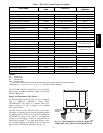
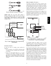
Smoke Detectors
Smoke detectors are available as factory--installed options
on 548J*14D models. Smoke detectors may be specified
for Supply Air only or for Return Air without or with
economizer or in combination of Supply Air and Return
Air. Return Air smoke detectors are arranged for vertical
return configurations only. All components necessary for
operation are factory--provided and mounted. The unit is
factory--configured for immediate smoke detector
shutdown operation; additional wiring or modifications to
unit terminal board may be necessary to complete the unit
and smoke detector configuration to meet project
requirements.
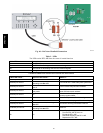
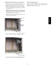
Units equipped with factory--optional Return Air smoke
detectors require a relocation of the sensor module at unit
installation. See “Completing Installation of Return Air
Smoke Sensor:” on page 29 for details.
System —
The smoke detector system consists of a four--wire
controller and one or two sensors. Its primary function is
to shut down the rooftop unit in order to prevent smoke
from circulating throughout the building. It is not to be
used as a life saving device.
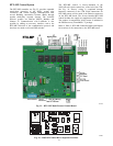
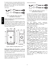
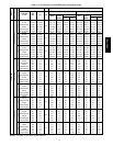
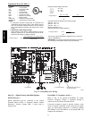
Controller —
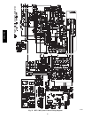
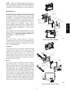
The controller (see Fig. 49) includes a controller housing,
a printed circuit board, and a clear plastic cover. The
controller can be connected to one or two compatible duct
smoke sensors. The clear plastic cover is secured to the
housing with a single captive screw for easy access to the
wiring terminals. The controller has three LEDs (for
Power, Trouble and Alarm) and a manual test/reset button,
all located on the cover face.
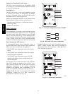
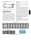
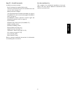
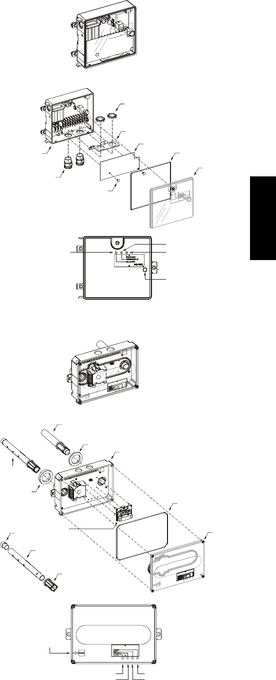
Sensor —
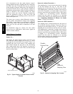
The sensor (see Fig. 50) includes a plastic housing, a
printed circuit board, a clear plastic cover, a sampling
tube inlet and an exhaust tube. The sampling tube (when
used) and exhaust tube are attached during installation.
The sampling tube varies in length depending on the size
of the rooftop unit. The clear plastic cover permits visual
inspections without having to disassemble the sensor. The
cover attaches to the sensor housing using four captive
screws and forms an airtight chamber around the sensing
electronics. Each sensor includes a harness with an RJ45
terminal for connecting to the controller. Each sensor has
four LEDs (for Power, Trouble, Alarm and Dirty) and a
manual test/reset button (on the left--side of the housing).
Duct smoke sensor
controller
Fastener
(2X)
Controller cover
Conduit nuts
(supplied by installer)
Conduit support plate
Cover gasket
(ordering option)
Conduit couplings
(supplied by installer)
Terminal block cover
Controller housing
and electronics
Alarm
Power
Test/reset
switch
Trouble
C08208
Fig. 49 -- Controller Assembly
Duct smoke sensor
See
Detail A
Exhaust tube
Plug
Sampling tube
(ordered separately)
Intake
gasket
Cover gasket
(ordering option)
TSD-CO2
(ordering option)
Sensor housing
and electronics
Exhaust gasket
Coupling
Sensor cover
Detail A
Magnetic
test/reset
switch
Alarm
Trouble
Power
Dirty
C08209
Fig. 50 -- Smoke Detector Sensor
548J*14D