


28
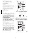
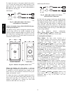
Air is introduced to the duct smoke detector sensor’s
sensing chamber through a sampling tube that extends into
the HVAC duct and is directed back into the ventilation
system through a (shorter) exhaust tube. The difference in
air pressure between the two tubes pulls the sampled air
through the sensing chamber. When a sufficient amount of
smoke is detected in the sensing chamber, the sensor
signals an alarm state and the controller automatically
takes the appropriate action to shut down fans and
blowers, change over air handling systems, notify the fire
alarm control panel, etc.
The sensor uses a process called differential sensing to
prevent gradual environmental changes from triggering
false alarms. A rapid change in environmental conditions,
such as smoke from a fire, causes the sensor to signal an
alarm state but dust and debris accumulated over time
does not.
For installations using two sensors, the duct smoke
detector does not differentiate which sensor signals an
alarm or trouble condition.
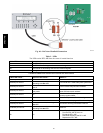
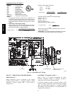
Smoke Detector Locations
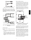
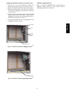
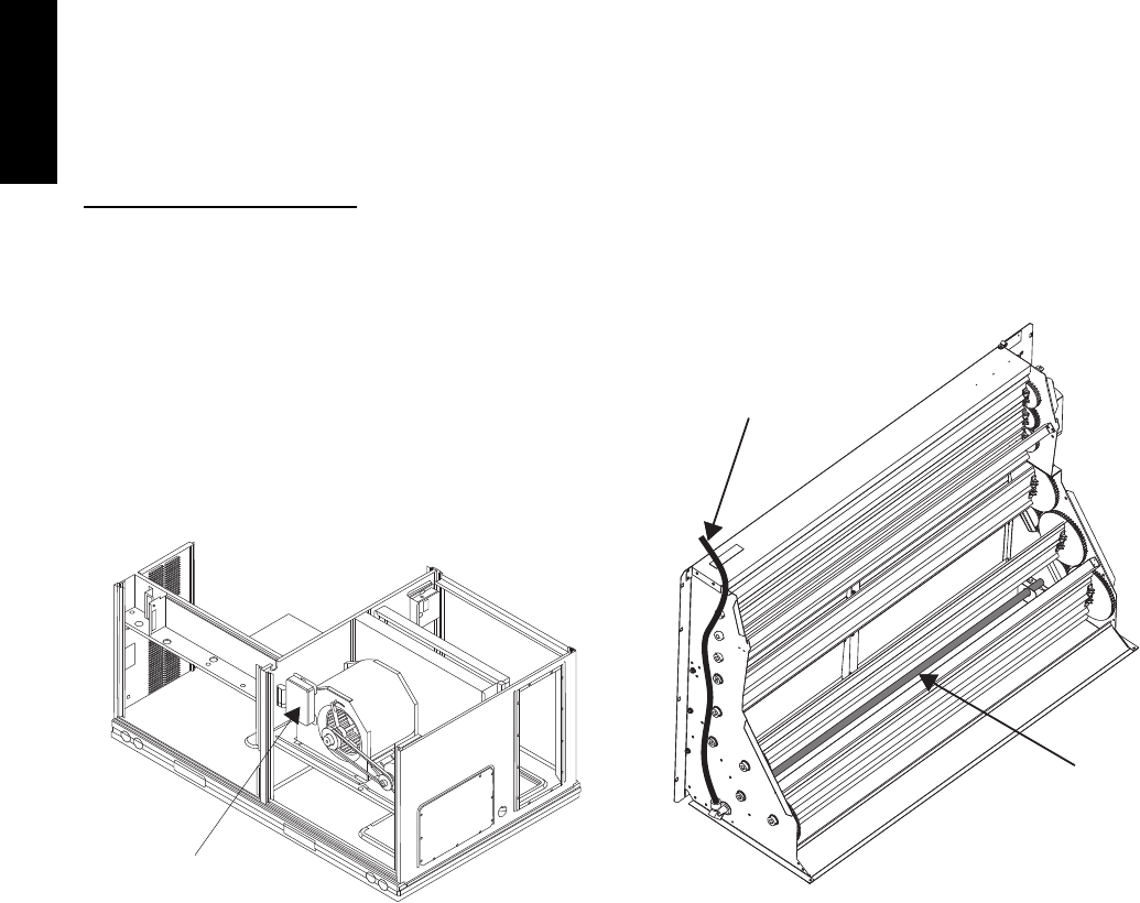
Supply Air —
The Supply Air smoke detector sensor is located to the
left of the unit’s indoor (supply) fan. See Fig. 51. Access
is through the left side blower access panel. There is no
sampling tube used at this location. The sampling tube
inlet extends through the side plate of the fan housing
(into a high pressure area). The controller is located on a
bracket to the right of the return filter, accessed through
the lift--off filter panel.
Smoke Detector Sensor
C08245
Fig. 51 -- Typical Supply Air Smoke Detector Sensor
Location
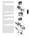
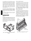
Return Air without Economizer —
The sampling tube is located across the return air opening
on the unit basepan. See Fig. 52. The holes in the
sampling tube face downward, into the return air stream.
The sampling tube is connected via tubing to the return air
sensor that is mounted on a bracket high on the partition
between return filter and controller location. (This sensor
is shipped in a flat--mounting location. Installation
requires that this sensor be relocated to its operating
location and the tubing to the sampling tube be connected.
See “Completing Installation of Return Air Smoke
Sensor:” on page 29 for details.)
Return Air with Economizer —
The sampling tube is inserted through the side plates of
the economizer housing, placing it across the return air
opening on the unit basepan. See Fig. 52. The holes in the
sampling tube face downward, into the return air stream.
The sampling tube is connected via tubing to the return air
sensor that is mounted on a bracket high on the partition
between return filter and controller location. (This sensor
is shipped in a flat--mounting location. Installation
requires that this sensor be relocated to its operating
location and the tubing to the sampling tube be connected.
See the following installation procedure.)
Return Air
Sampling Tube
Flexible
Exhaust Tube
C10330
Fig. 52 -- Return Air Sampling Tube Location
548J*14D