


11
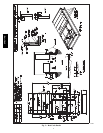
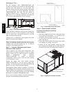
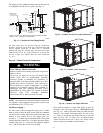
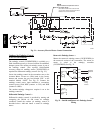
The piping for the condensate drain and external trap can
be completed after the unit is in place. See Fig. 15.
NOTE: Trap should be deep enough to offset maximum unit static
difference. A 4” (102) trap is recommended.
MINIMUM PITCH
1” (25mm) PER
10’ (3m) OF LINE
BASE RAIL
OPEN
VENT
TO ROOF
DRAIN
DRAIN PLUG
ROOF
CURB
SEE NOTE
2˝ (51) MIN
C08022
Fig. 15 -- Condensate Drain Piping Details
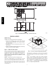
All units must have an external trap for condensate
drainage. Install a trap at least 4-in. (102 mm) deep and
protect against freeze-up. If drain line is installed
downstream from the external trap, pitch the line away
from the unit at 1-in. per 10 ft (25 mm in 3 m) of run. Do
not use a pipe size smaller than the unit connection
(
3
/
4
-in.).
Step 10 — Make Electrical Connections
ELECTRICAL SHOCK HAZARD
Failure to follow this warning could result in personal
injury or death.
Do not use gas piping as an electrical ground. Unit
cabinet must have an uninterrupted, unbroken
electrical ground to minimize the possibility of
personal injury if an electrical fault should occur. This
ground may consist of electrical wire connected to
unit ground lug in control compartment, or conduit
approved for electrical ground when installed in
accordance with NEC (National Electrical Code);
ANSI/NFPA 70, latest edition (in Canada, Canadian
Electrical Code CSA [Canadian Standards
Association] C22.1), and local electrical codes.
!
WARNING
NOTE: Check all factory and field electrical connections
for tightness. Field--supplied wiring shall conform with
the limitations of 63_F(33_C) rise.
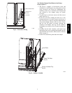
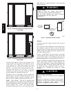
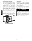
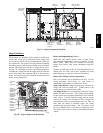
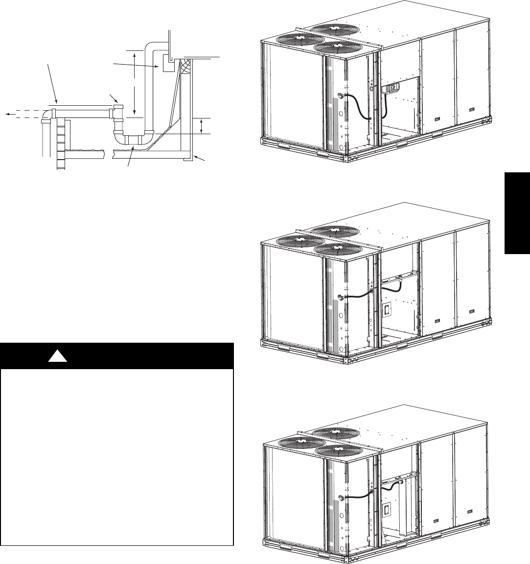
Field Power Supply —
For those units without through--the--curb power, conduit
must be used to route the main power from the condenser
end of the unit to either the factory option disconnect, the
bottom of the control box or the single point box
accessory. 1” conduit is provided behind the access panel
located under the control box. For those units that require
conduit larger than 1”, it must be field supplied. Figures
16, 17 and 18 show the various wire routings.
C10010
Fig. 16 -- Conduit into Factory Option Disconnect
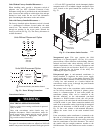
C10011
Fig. 17 -- Conduit into Control Box
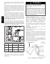
C10012
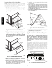
Fig. 18 -- Conduit into Single Point Box
If the field disconnect is larger than 100A, it must be
attached to the unit using accessory CRDISBKT001A00
(see Fig. 19). Follow the instructions provided with this
accessory. For smaller field disconnects, be sure to use
1
/
2
” screws to mount the disconnect directly to the end
panel (see Fig. 20). In either case, set the disconnect
vertical location on the unit so that a 90_ fitting can be
used to connect the conduit to the disconnect.
548J*14D