


18
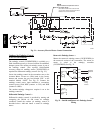
NOTE:
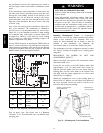
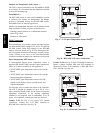
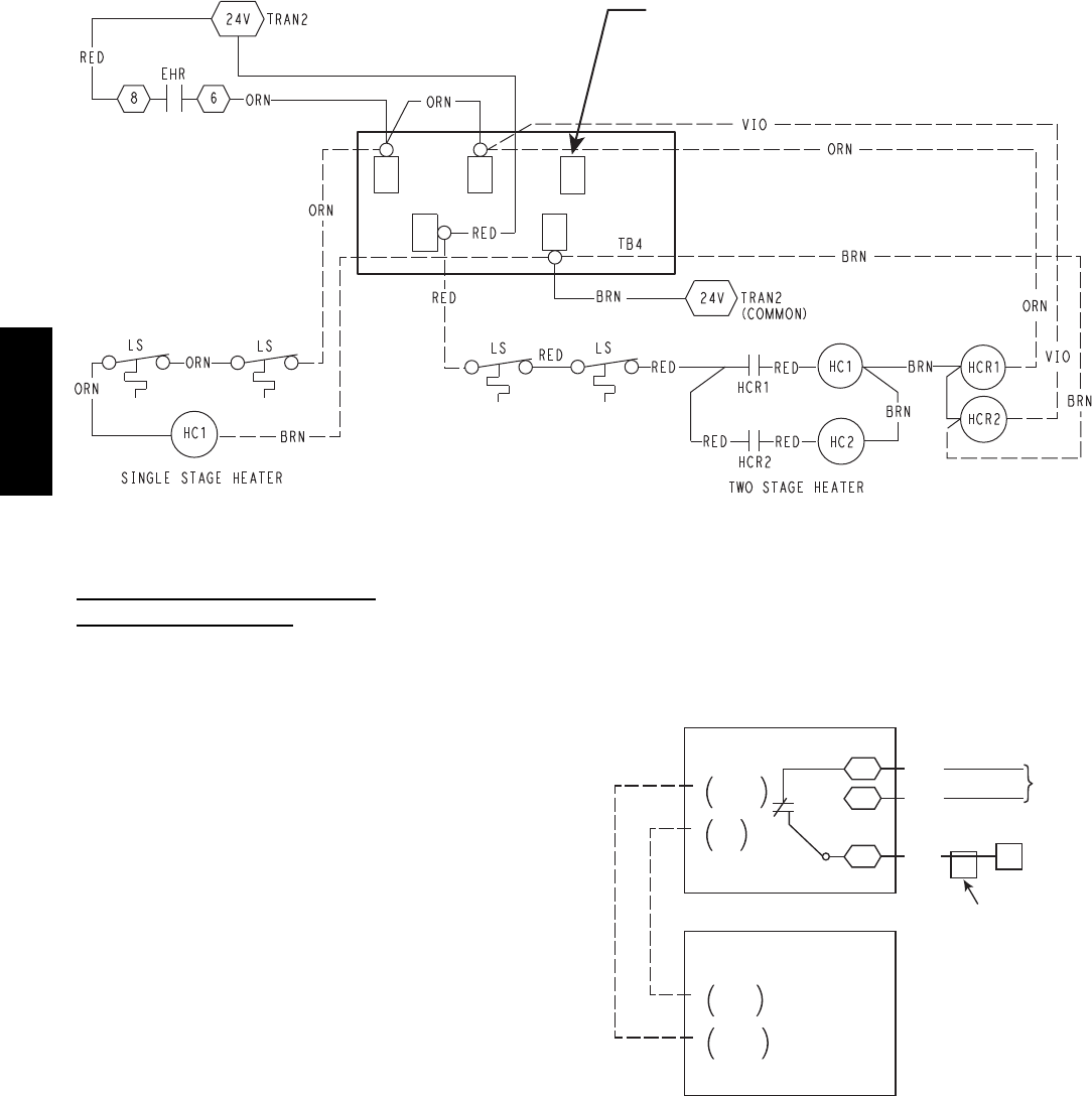
Optional Outdoor Temperature Control
at One Heater Stage –
Move either heater wire to this terminal
and connect outdoor temperature switch
between 2nd and 3rd terminals.
C10354
Fig. 31 -- Accessory Electric Heater Control Connections
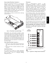
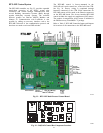
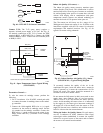
Outdoor Air Enthalpy Control
(PNO 33CSENTHSW)
The enthalpy control (33CSENTHSW) is available as a
field--installed accessory to be used with the EconoMi$er2
damper system. The outdoor air enthalpy sensor is part of
the enthalpy control. (The separate field--installed
accessory return air enthalpy sensor (33CSENTSEN) is
required for differential enthalpy control. See Fig. 32.)
Locate the enthalpy control in the economizer next to the
Actuator Motor. Locate two GRA leads in the factory
harness and connect the gray lead labeled “ESL” to the
terminal labeled “LOW”. See Fig. 32. Connect the
enthalpy control power input terminals to economizer
actuator power leads RED (connect to 24V) and BLK
(connect to GND).
The outdoor enthalpy changeover setpoint is set at the
enthalpy controller.
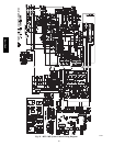
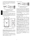
Differential Enthalpy Control —
Differential enthalpy control is provided by sensing and
comparing the outside air and return air enthalpy
conditions. Install the outdoor air enthalpy control as
described above. Add and install a return air enthalpy
sensor.
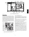
Return Air Enthalpy Sensor —
Mount the return--air enthalpy sensor (33CSENTSEN) in
the return--air section of the economizer. The return air
sensor is wired to the enthalpy controller
(33CSENTHSW). See Fig. 32.
– 4-20 mA
In
+ VDC
Out
– 4-20 mA
Out
+ 24-36
VDC In
7
ESL
CTB
ECON
LOW
GND
24V
Enthalpy
Switch
Return Air
Enthalpy Sensor
GRA
BLK
RED
Factory
Wiring
Harness
ECONO
MOTOR
B
L
K
R
E
D
C10282
Fig. 32 -- Outside and Return Air Enthalpy Sensor
Wiring
548J*14D