


21
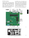
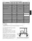
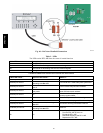
Table 2 – RTU--MP Controller Inputs and Outputs
POINT NAME
BACnet OBJECT
NAME
TYPE OF I/O
CONNECTION PIN
NUMBER S
INPUTS
Space Temperature Sensor sp tsens AI (10K Thermistor) J20 --- 1, 2
Supply Air Temperature sat AI (10K Thermistor) J2---1, 2
Local Outside Air Temperature Sensor oatsens AI (10K Thermistor) J2---3, 4
Space Temperature Offset Pot sptopot AI (100K Potentiometer) J20 --- 3
Indoor Air Quality iaq AI (4 --- 20 ma) J4---2, 3
Outdoor Air Quality oaq AI (4 --- 20 ma) J4---5, 6
Safety Chain Feedback safety DI (24 VAC) J1---9
Compressor Safety compstat DI (2 4 VAC) J1---2
Fire Shutdown firedown DI (2 4 VAC) J1 --- 10
Enthalpy Switch enthalpy DI (2 4 VAC) J2---6, 7
Humidistat Input Status humstat DI (2 4 VAC) J5---7, 8
CONFIGURABLE INPUTS*
Space Relative Humidity sprh AI (4 --- 20 ma)
J4 --- 2,3 or J4 --- 5,6
Outside Air Relative Humidity oarh AI (4 --- 20 ma)
Supply Fan Status fanstat DI (2 4 VAC)
J5---1,2 or J5---3,4 or
J5 5,6 or J5---7,8
Filter Status filtstat DI (2 4 VAC)
Remote Occupancy Input rem o cc DI (24 VAC)
OUTPUTS
Economizer Commanded Position econocmd 4---20ma J2---5
SupplyFanRelayState sf DO Relay (24VAC , 1A) J1---4
Compressor 1 Relay State comp_1 DO Relay (24VAC , 1A) J1---8
Compressor 2 Relay State comp_2 DO Relay (24VAC , 1A) J1---7
Heat Stage 1 Relay State heat_1 DO Relay (24VAC , 1A) J1---6
Heat Stage 2 Relay State heat_2 DO Relay (24VAC , 1A) J1---5
Po wer Exhaust Relay State aux_2 DO Relay (24VAC , 1A) J11 --- 3
Dehumidification Relay State humizer DO Relay (24VAC, 1A) J11 --- 7, 8
LEGEND
AI --- Analog Input
AO --- Analog Output
DI --- Discrete Input
DO --- Discrete Output
* These inputs (if installed) take the pl ace of the default input on the specific channel according to schematic.
Parallel pins J5 --- 1 = J2 --- 6, J5 --- 3 = J1 --- 10, J5 --- 5 = J1 --- 2 are used for field --- installation.
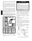
The RTU--MP controller requires the use of a Bryant
space sensor. A standard thermostat cannot be used with
the RTU--MP system.
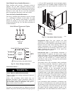
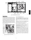
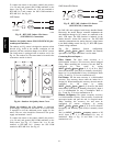
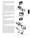
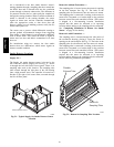
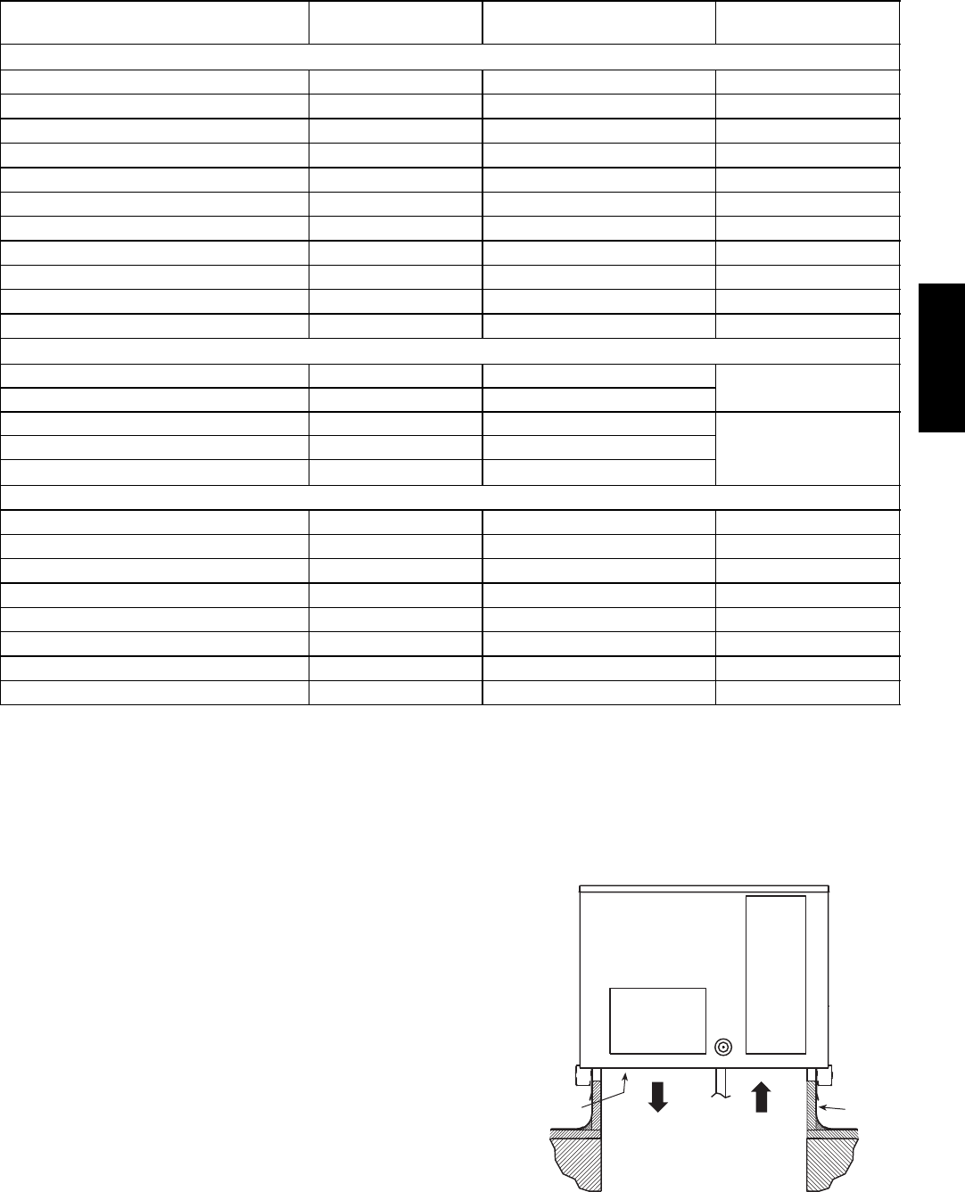
Supply Air Temperature (SAT) Sensor —
On FIOP--equipped 548J*14D unit, the unit is supplied
with a supply--air temperature (SAT) sensor
(33ZCSENSAT). This sensor is a tubular probe type,
approx 6--inches (12.7 mm) in length. It is a nominal
10--k ohm thermistor.
The SAT is factory--wired. The SAT probe is wire--tied to
the supply--air opening (on the horizontal opening end) in
its shipping position. Remove the sensor for installation.
Re--position the sensor in the flange of the supply--air
opening or in the supply air duct (as required by local
codes). Drill or punch a
1
/
2
--in. hole in the flange or duct.
Use two field--supplied, self--drilling screws to secure the
sensor probe in a horizontal orientation. See Fig. 36.
SUPPLY AIR
RETURN AIR
SUPPLY AIR
TEMPERATURE
SENSOR
ROOF
CURB
C10020
Fig. 36 -- Typical Mounting Location for Supply Air
Temperature (SAT) Sensor on Small Rooftop Units
548J*14D