


14
the transformer; however, the conduit must be routed so
that all wiring is either in the conduit or behind the access
panel.
If the convenience outlet transformer is connected to the
line side of the factory disconnect option, route the wires
through the web bushing located on the bottom of the
disconnect box. For the load side wiring to the factory
option disconnect, route the wires through the hole on the
right side of the disconnect. Be sure to create a drip loop
at least 6” long.
Duty Cycle: the unit--powered convenience outlet has a
duty cycle limitation. The transformer is intended to
provide power on an intermittent basis for service tools,
lamps, etc; it is not intended to provide 15--amps loading
for continuous duty loads (such as electric heaters for
overnight use). Observe a 50% limit on circuit loading
above 8--amps (i.e., limit loads exceeding 8--amps to 30
minutes of operation every hour).
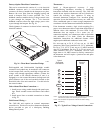
Test the GFCI receptacle by pressing the TEST button on
the face of the receptacle to trip and open the receptacle.
Check for proper grounding wires and power line phasing
if the GFCI receptacle does not trip as required. Press the
RESET button to clear the tripped condition.
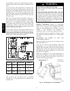
C08283
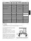
UNIT
VOLTAGE
CONNECT
AS
PRIMARY
CONNECTIONS
TRANSFORMER
TERMINALS
208,
230
240
L1: RED +YEL
L2: BLU + GRA
H1 + H3
H2 + H4
460 480
L1: RED
Splice BL U + YEL
L2: GRA
H1
H2 + H3
H4
575 600
L1: RED
L2: GRA
H1
H2
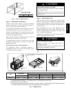
Fig. 24 -- Unit Powered Convenience Outlet Wiring
Fuse on power type: The factory fuse is a Bussman
“Fusetron” T--15, non--renewable screw--in (Edison base)
type plug fuse.
ELECTRICAL OPERATION HAZARD
Failure to follow this warning could result in personal
injury or death.
Using unit--mounted convenience outlets: Units with
unit--mounded convenience outlet circuits will often
require that two disconnects be opened to de--energize
all power to the unit. Treat all units as electrically
energized until the convenience outlet power is also
checked and de--energization is confirmed. Observe
National Electrical Code Article 210, Branch Circuits,
for use of convenience outlets.
!
WARNING
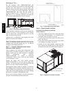
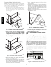
Installing Weatherproof Cover: A weatherproof
while-in-use cover for the factory-installed convenience
outlets is now required by UL standards. This cover
cannot be factory-mounted due its depth; it must be
installed at unit installation. For shipment, the
convenience outlet is covered with a blank cover plate.
The weatherproof cover kit is shipped in the unit’s control
box. The kit includes the hinged cover, a backing plate
and gasket.
DISCONNECT ALL POWER TO UNIT AND
CONVENIENCE OUTLET.
Remove the blank cover plate at the convenience outlet;
discard the blank cover.
Loosen the two screws at the GFCI duplex outlet, until
approximately
1
/
2
-in (13 mm) under screw heads are
exposed. Press the gasket over the screw heads. Slip the
backing plate over the screw heads at the keyhole slots
and align with the gasket; tighten the two screws until
snug (do not over-tighten).
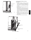
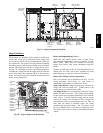
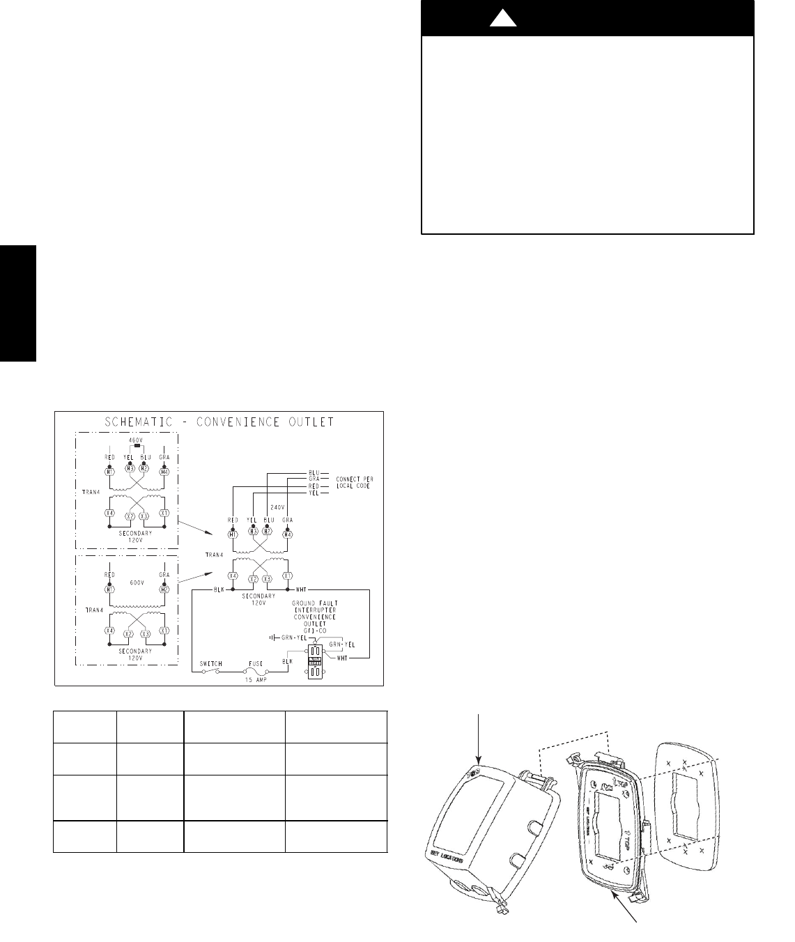
Mount the weatherproof cover to the backing plate as
shown in Fig. 25. Remove two slot fillers in the bottom of
the cover to permit service tool cords to exit the cover.
Check for full closing and latching.
RECEPTACLE
NOT INCLUDED
COVER – WHILE-IN-USE
WEATHERPROOF
BASE PLATE FOR
GFCI RECEPTACLE
C09022
Fig. 25 -- Weatherproof Cover Installation
548J*14D