


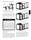
15
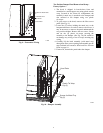
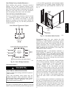
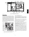
Factory--Option Thru--Base Connections —
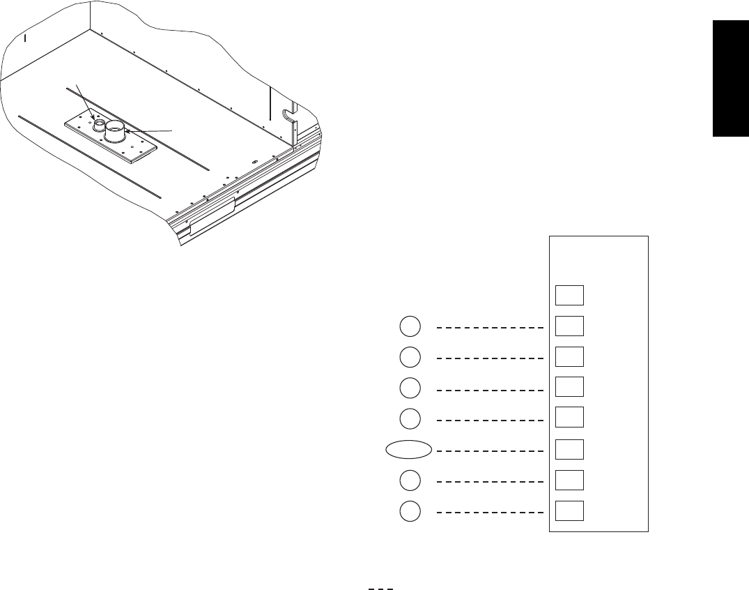
This service connection kit consists of a
1
/
2
--in electrical
bulkhead connector and a 1
1
/
2
--in electrical bulkhead
connector, all factory--installed to the basepan cover plate.
Remove the cover plate from the shipping bracket and
attach to basepan with 8 screws provided. The
1
/
2
-- i n
bulkhead connector enables the low--voltage control wires
to pass through the basepan. The 1
1
/
2
--in electrical
bulkhead connector allows the high--voltage power wires
to pass through the basepan. See Fig. 26.
Check tightness of connector lock nuts before connecting
electrical conduits.
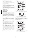
LOW VOLTAGE
CONDUIT
CONNECTOR
HIGH VOLTAGE
CONDUIT
CONNECTOR
C10017
Fig. 26 -- Thru--Base Connection Fittings
Field--supplied and field--installed liquidtight conduit
connectors and conduit may be attached to the connectors
on the basepan. Pull correctly rated high voltage and low
voltage wires through appropriate conduits. Connect the
power conduit to the internal disconnect (if unit is so
equipped) or to the external disconnect (through unit side
panel). Remove one of the two knockouts located on the
bottom left side of the unit control box. Use this hole for
the control conduit.
Units without Thru--Base Connections —
1. Install power wiring conduit through side panel open-
ings. Install conduit between disconnect and control
box.
2. Install power lines to terminal connections as shown
in Fig. 22.
Field Control Wiring —
The 548J*14D unit requires an external temperature
control device. This device can be a thermostat emulation
device provided as part of a third--party Building
Management System.
Thermostat —
Install a Bryant--approved accessory 2 stage
Cooling/Heating thermostat according to installation
instructions included with the accessory. The 548J*14D
models do not require a thermostat with an O function to
control the reversing valve operation. If using an
electronic thermostat, configure it for “non--heat pump”
operation. Locate the thermostat accessory on a solid wall
in the conditioned space to sense average temperature in
accordance with the thermostat installation instructions.
If the thermostat contains a logic circuit requiring 24--v
power, use a thermostat cable or equivalent single leads of
different colors with minimum of seven leads. If the
thermostat does not require a 24--v source (no “C”
connection required), use a thermostat cable or equivalent
with minimum of six leads. Check the thermostat
installation instructions for additional features which
might require additional conductors in the cable.
For wire runs up to 50 ft. (15 m), use no. 18 AWG
(American Wire Gage) insulated wire (35_C minimum).
For50to75ft.(15to23m),useno.16AWGinsulated
wire (35_C minimum). For over 75 ft. (23 m), use no. 14
AWG insulated wire (35_C minimum). All wire sizes
larger than no. 18 AWG cannot be directly connected to
the thermostat and will require a junction box and splice
at the thermostat.
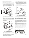
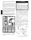
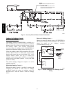
X
C
G
W2
C
W2
G
W1
O/B/Y2
Y2
R
W1
R
Y1
Y1
T
H
E
R
M
O
S
T
A
T
(Note 1)
(Note 2)
Note 1: Typical multi-function marking. Follow manufacturer’s configuration
instructions to select Y2. Do not configure for O output.
Note 2: W2 connection not required on units without electric heating.
Field Wiring
Central
Terminal
Board
Typical
Thermostat
Connections
C09012
Fig. 27 -- Typical Low--Voltage Control Connections
548J*14D