


24
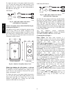
To connect the sensor to the control, identify the positive
(4 to 20 mA) and ground (SIG COM) terminals on the
sensor. See Fig. 42. Connect the 4--20 mA terminal to
RTU--MP J4--2 and connect the SIG COM terminal to
RTU--MP J4--3. See Fig. 43.
SEN
COM
J4-2
J4-3
IAQ Sensor
24 VAC
C08462
Fig. 43 -- RTU--MP / Indoor CO
2
Sensor
(33ZCSENCO2) Connections
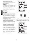
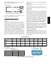
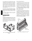
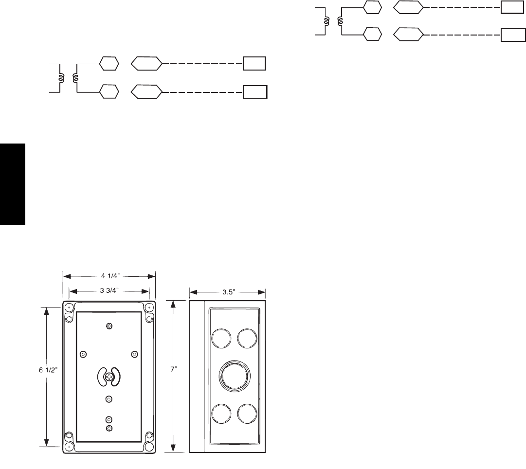
Outdoor Air Quality Sensor (PNO 33ZCSENCO2 plus
weatherproof enclosure) —
The outdoor air CO
2
sensor is designed to monitor carbon
dioxide (CO
2
) levels in the outside ventilation air and
interface with the ventilation damper in an HVAC system.
The OAQ sensor is packaged with an outdoor cover. See
Fig. 44. The outdoor air CO
2
sensor must be located in the
economizer outside air hood.
COVER REMOVED SIDE VIEW
C07135
Fig. 44 -- Outdoor Air Quality Sensor Cover
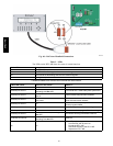
Wiring the Outdoor Air CO
2
Sensor: A dedicated
power supply is required for this sensor. A two--wire cable
is required to wire the dedicated power supply for the
sensor. The two wires should be connected to the power
supply and terminals 1 and 2.
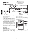
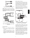
To connect the sensor to the control, identify the positive
(4 to 20 mA) and ground (SIG COM) terminals on the
OAQ sensor. See Fig. 42. Connect the 4 to 20 mA
terminal to RTU--MP J4--5. Connect the SIG COM
terminal to RTU--MP J4--6. See Fig. 45.
SEN
COM
J4-5
J4-6
OAQ Sensor/RH Sensor
24 VAC
C08463
Fig. 45 -- RTU--MP / Outdoor CO
2
Sensor
(33ZCSENCO2) Connections
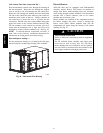
On 548J*14D units equipped with factory--installed Smoke
Detector(s), the smoke detector controller implements the
unit shutdown through its NC contact set connected to the
unit’s CTB input. The FSD function is initiated via the
smoke detector’s Alarm NO contact set. The RTU--MP
controller communicates the smoke detector’s tripped status
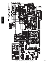
to the BAS building control. See Fig. 35, RTU--MP System
Control wiring schematic.
The Fire Shutdown Switch configuration,
MENU
→
Config
→
Inputs
→
input 5, identifies the normally
open status of this input when there is no fire alarm.
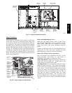
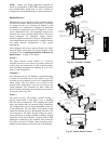
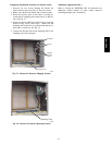
Connecting Discrete Inputs —
Filter Status: The filter status accessory is a
field--installed accessory. This accessory detects plugged
filters. When installing this accessory, the unit must be
configured for filter status by setting
MENU
→
Config
→
Inputs
→
input3,5,8,or9to Filter
Status and normally open (N/O) or normally closed (N/C).
Input 8 or 9 is recommended for easy of installation. Refer
to Fig. 33 and Fig. 35 for wire terminations at J5.
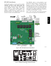
Fan Status: The fan status accessory is a field--installed
accessory. This accessory detects when the indoor fan is
blowing air. When installing this accessory, the unit must be
configured for fan status by setting
MENU
→
Config
→
Inputs
→
input3,5,8,or9to Fan Status
and normally open (N/O) or normally closed (N/C). Input 8
or 9 is recommended for easy of installation. Refer to
Fig. 33 and Fig. 35 for wire terminations at J5.
Remote Occupancy: The remote occupancy accessory
is a field--installed accessory. This accessory overrides the
unoccupied mode and puts the unit in occupied mode.
When installing this accessory, the unit must be
configured for remote occupancy by setting
MENU
→
Config
→
Inputs
→
input3,5,8,or9to Remote
Occupancy and normally open (N/O) or normally closed
(N/C).
Also set MENU
→
Schedules
→
occupancy source to DI
on/off. Input 8 or 9 is recommended for easy of
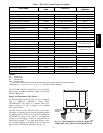
installation. Refer to Fig. 33 and Table 2 for wire
terminations at J5.
548J*14D