


57
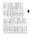
11 NO PREVIOUS CODE – Status codes
are erased after 72 hours or can be
manually erased by putting setup switch
SW1-1 in the ON position and jumpering
R, W/W1, and Y/Y2 simultaneously until
status code #11 is flashed. Run system
through a low-heat, high-heat, or cooling
cycle to check system.
12
BLO
WER ON AFTER POWER UP –
(115V OR 24V) – Normal operation.
Blower runs for 90 seconds, if unit is
powered up during a call for heat (R-
W/W1 closed) or when (R-W/W1 opens)
during the blower on-delay period.
13
LIMIT CIRCUIT LOCKOUT – Lockout
occurs if the limit, draft safeguard, flame
rollout, or blocked vent switch* (if used)
is open longer than 3 minutes or 10
successive limit tr
ips occurred dur
ing
high-heat. Control will auto-reset after
3
hours. See code 33.
14
IGNITION LOCKOUT – System failed to
ignite gas and prove flame in 4 attempts.
Control will auto-reset after 3 hours.
See status code 34.
15 BLOWER MOTOR LOCKOUT –
Indicates
the b
lo
wer failed to reach 250 RPM or
the b
lo
wer failed to communicate within
30 seconds after being turned ON in two
successive heating cycles
. Control will
auto-reset after 3 hours. See code 41.
21 GAS HEATING LOCKOUT – Turn off
power and wait 5 minutes to retry.
Check for:
- Stuck closed gas valve relay on control.
- Miswire or short to gas valve wire.
22 ABNORMAL FLAME-PROV
ING
SIGNAL
Flame is proved while gas valve is de-
energiz
ed.
Inducer will run until fault is
cleared. Check for:
- Stuck open or leaky gas valve.
23 PRESSURE SWITCH DID NOT OPEN
Check for:
- Obstructed pressure tube.
- Pressure switch stuck closed.
24 SECONDARY VOLTAGE FUSE IS OPEN
Check for:
- Short circuit in secondary voltage
(24V) wir
ing including thermostat
leads. Disconnect thermostat leads
to isolate short circuit.
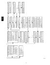
32 LOW-HEAT PRESSURE SWITCH DID
NOT CLOSE OR REOPENED – If open
longer than 5 minutes, inducer shuts off
for 15 minutes before retry. If opens
during blower on-delay period, blower will
come on for the selected blower off-delay.
Check for:
- Proper vent sizing.
- Low inducer voltage (115V).
- Low inlet gas pressure (if LGPS used).
- Inadequate combustion air supply.
- Disconnected or obstructed pressure
tubing.
- Defective inducer motor.
- Defective pressure switch.
- Excessive wind.
- Restricted vent.
33 LIMIT CIRCUIT F
AU
LT – Indicates the
limit, draft safeguard, flame rollout, or
blocked vent switch* (if used) is open or
the furnace is operating in high-heat only
mode due to 2 successive low-heat limit
trips.
Blower will run for 4 min. or until
open switch remakes whichever is longer.
If open
longer than 3 min.,
code
change
s
to lockout #13. If open less than 3 min.
status code #33 continues to flash until
blow
er shuts
off. F
lame rollout switch and
BVSS requires manual reset.
Check for:
-Dir
ty filter or restricted duct system.
- Loose blower wheel.
- Defective switch or connections.
- Inadequate combustion air supply
(flame rollout switch open).
- Restr
icted vent.
- Proper vent sizing.
- Excessive wind.
34
IGNITION PROVING
FAILURE – If flame
is not sensed during the trial for ignition
period, the control will repeat the ignition
sequence 3 more times before lockout
#14 occurs. If flame signal is lost
during
the blo
wer on-delay period, blower will
come on for the selected blower off-delay.
Check the following items first before
proceeding to the next step.
- Gas valve turned off.
- Manual shut-off valve.
- Green/Yellow wire MUST be connected
to furnace sheet metal.
- Flame sensor must not be grounded.
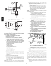
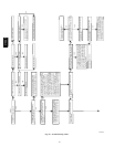
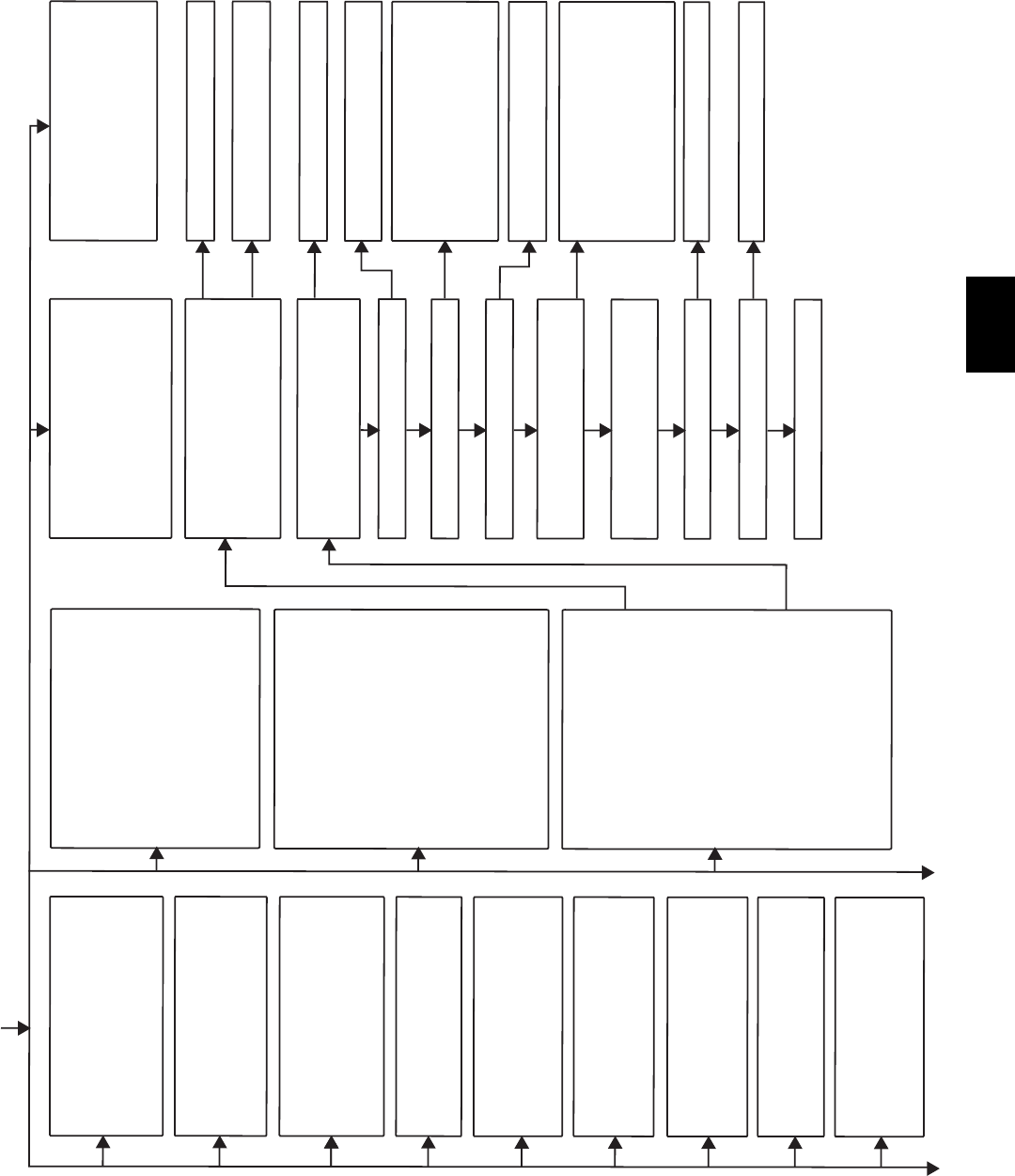
To determine whether the problem is in
the gas valve, igniter, or flame sensor the
system can be operated in component
test mode. To check the igniter remove
the R thermostat connection from the
control, reset power, and put setup switch
SW1-6 in the ON position to start the
component test. Does the igniter glow
orange/white by the end of the 15 second
warm-up period?
43 LOW-HEAT PRESSURE SWITCH OPEN
WHILE HIGH-HEAT PRESSURE
SWITCH IS CLOSED - Chec
k for:
- Low-heat pressure switch stuck open.
- Disconnected or obstructed pressure
tube.
- Miswired pressure switches.
-L
ow inlet gas pressure (if LGPS used).
Unplug igniter harness from control and
repeat component test by
tur
ning setup switch
SW1-6 OFF and then bac
k ON. Check for
115V between pin 3 and NEUTRAL-L2 on
the control. Was 115V present for the 15
second period?
Reconnect the R thermostat lead and set
t
hermostat
to call for heat. Connect vo
ltmeter
across gas valve connections. Does gas
valve receive 24V?
Does gas valve open and allow gas to flow?
Do the main burners ignite?
Do the main burners stay on?
Repeat call for heat and check flame sensor
current during trial for ignition period. Is the
DC microamps below 0.5?
Clean flame sensor with fine steel wool and
recheck current. Nominal current is
4.0 to
6.0 microamps.
Is current near typical value?
Will main burners ignite and stay on?
Fixed.
45 CONTROL CIRCUITRY LOCKOUT
Auto-reset after 1 hour lockout due to:
- Flame circuit failure.
- Gas valve relay stuck open.
- Software check error.
Reset power to clear lockout.
Replace control if code repeats.
Replace furnace control.
Check for continuity in the harness and
igniter. Replace defective component.
YES
NO
YES
YES
YES
NO
YES
Chec
k connections. If OK, replace control.
Chec
k that all gas v
alves are turned on.
Replace valve.
Chec
k for:
- Inadequate flame carr
yover or rough
ignition.
-L
ow inlet gas pressure.
-P
roper firing rate.
-B
locked or incorrect carry- over gap.
(.045” nominal)
Allow blower to come on and repeat test
to check for intermittent operation.
Chec
k connections and retry. If current is
near typical value (4.0-6.0 nominal) and
burners will not stay on, repeat check in high-
heat. If burners will still not stay on replace
control. If burners operate in high-heat then
switch to low-heat,check manifold pressure.
If OK, check burner carryover and flame
sensor location.
Replace electrode.
Replace furnace control.
NO
NO
NO
YES
NO
NO
NO
NO
YES
* Blocked vent switch used in Chimney Adapter Kit
YES
YES
A02108B
315AAV