


55
blower airflow after the heating cycle is completed. In
high--heat, the furnace control CPU will drop the blower
motor BLWM to low--heat airflow during the selected
blower--OFF delay period before transitioning to continu-
ous--blower airflow.
When the thermostat “calls for low--cooling”, the blower
motor BLWM will switch to operate at low--cooling air-
flow. When the thermostat is satisfied, the blower motor
BLWM will operate an additional 90 seconds at low--cool-
ing airflow before transitioning back to continuous--
blower airflow.
When the thermostat “calls for high--cooling”, the blower
motor BLWM will operate at high cooling airflow. When
the thermostat is satisfied, the blower motor BLWM will
operate an additional 90 seconds at high--cooling airflow
before transitioning back to continuous--blower airflow.
When the R--to--G circuit is opened, the blower motor
BLWM will continue operating for an additional 5
seconds, if no other function requires blower motor
BLWM operation.
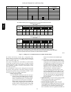
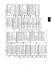
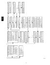
Continuous Blower Speed Selection from Thermostat
To select different continuous--blower airflow from the
room thermostat, momentarily turn off the FAN switch or
push button on the room thermostat for 1--3 seconds after
the blower motor BLWM is operating. The furnace control
CPU will shift the continuous--blower airflow from the
factory setting to the next highest CF selection airflow as
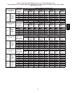
shown in Fig. 57. Momentarily turning off the FAN switch
again at the thermostat will shift the continuous--blower
airflow up one more increment. If you repeat this proced-
ure enough you will eventually shift the continuous--
blower airflow to the lowest CF selection as shown in Fig.
57. The selection can be changed as many times as desired
and is stored in the memory to be automatically used fol-
lowing a power interruption.
NOTE: If the blower--off delay is set to the maximum, the
adjustable continuous--fan feature is locked (i.e., fan speed cannot
be changed from its current setting).
7. Heat pump
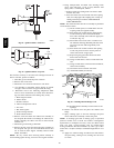
See Fig. 29 -- 32 for thermostat connections.
When installed with a heat pump, the furnace control auto-
matically changes the timing sequence to avoid long
blower off times during demand defrost cycles. Whenever
W/W1 is energized along with Y1 or Y/Y2, the furnace
control CPU will transition to or bring on the blower mo-
tor BLWM at cooling airflow, low--heat airflow, or the
mid--range airflow, whichever is lowest. The blower motor
BLWM will remain on until the main burners ignite then
shut OFF and remain OFF for 25 seconds before coming
back on at heating airflow. When the W/W1 input signal
disappears, the furnace control begins a normal inducer
post--purge period while changing the blower airflow. If
Y/Y2 input is still energized the furnace control CPU will
transition the blower motor BLWM airflow to cooling air-
flow. If Y/Y2 input signal disappears and the Y1 input is
still energized the furnace control CPU will transition the
blower motor BLWM to low--cooling airflow. If both the
Y1 and Y/Y2 signals disappear at the same time, the
blower motor BLWM will remain on at low--heat airflow
for the selected blower--OFF delay period. At the end of
the blower-- OFF delay, the blower motor BLWM will
shut OFF unless G is still energized, in which case the
blower motor BLWM will operate at continuous blower
airflow.
8. Component test
The furnace features a component test system to help dia-
gnose a system problem in the case of a component fail-
ure. To initiate the component test procedure, ensure that
there are no thermostat inputs to the control and all time
delays have expired. Turn on setup switch SW1--6. (See
Fig. 26.)
NOTE: The component test feature will not operate if the control
is receiving any thermostat signals or until all time delays have
expired.
The component test sequence is as follows:
a. The furnace control CPU turns the inducer motor ON
at high--heat speed and keeps it ON through step c.
b. After waiting 10 seconds the furnace control CPU
turns the hot surface igniter ON for 15 seconds, then
OFF.
c. The furnace control CPU then turns the blower motor
BLWM on at mid--range airflow for 15 seconds, then
OFF.
d. After shutting the blower motor OFF the furnace con-
trol CPU switches the inducer to low--heat speed for
10 seconds, then OFF.
NOTE: The EAC terminals are energized when the blower is
operating.
After the component test is completed, 1 or more status codes (11,
25, or 41) will flash. See component test section or Service Label
(Fig. 52) for explanation of status codes.
NOTE: To repeat component test, turn setup switch SW1--6 to
OFF and then back ON.
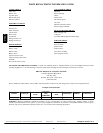
Wiring
Diagram
Refer to wiring diagram Fig. 53.
Tr
oubleshooting
Refer to the service label. (See Fig. 52—Service Label.)
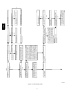
The Troubleshooting Guide (See Fig. 58.) can be a useful tool in
isolating furnace operation problems. Beginning with the word
“Start,” answer each question and follow the appropriate arrow to
the next item.
The Guide will help to identify the problem or failed component.
After replacing any component, verify correct operation
sequence.
A more detailed Troubleshooting Guide is available from your
distributor.
315AAV