


21
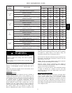
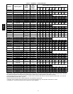
Table 7 – Electrical Data
FURNACE
SIZE
V OLT S ---
H ER TZ ---
PHASE
OPERATING
VOLTAGE RANGE
MAX. UNIT
AMPS
UNIT
AMPACITY
#
MAX . WIRE
LE NGT H --- F T (M )}
MAX . FUSE OR
CKT BKR AMPS {
MIN.
WIRE
GAUGE
Max. Min .
070---12/036070 115 ---60 --- 1 127 104 9.0 11.99 30 (9.0) 15 14
090---16/048090 115 ---60 --- 1 127 104 9.6 12.56 29 (8.8) 15 14
110---20/060110 115 ---60 --- 1 127 104 15.1 19.33 29 (8.8) 20 12
135---22/066135 115 ---60 --- 1 127 104 14.9 19.13 30 (9.0) 20 12
155---22/066155 115 ---60 --- 1 127 104 15.0 19.23 29 (8.8) 20 12
* Permissible limits of the voltage range at which the unit operates satisfactorily.
# Unit ampacity = 125 percent of largest operating component’s full load amps plus 100 percent of all other potential operating components’ (EAC, humidifier,
etc.) full load amps.
{Time---delay type is recommended.
}Length shown is as measured 1 way along wire path between furnace and service panel for maximum 2 percent voltage drop.
FIRE HAZARD
Failure to follow this warning could result in personal
injury, death, or property damage.
Do not connect aluminum wire between disconnect
switch and furnace. Use only copper wire.
!
WARNING
Use a separate, fused branch electrical circuit with a properly
sized fuse or circuit breaker for this furnace. See Table 7 for wire
size and fuse specifications. A readily accessible means of
electrical disconnect must be located within sight of the furnace.
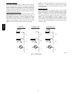
NOTE: Proper polarity must be maintained for 115--v wiring. If
polarity is incorrect, control LED status indicator light will flash
rapidly and furnace will NOT operate.
J--Box
Relocation
NOTE: If factory location of J--Box is acceptable, go to next
section (ELECTRICAL CONNECTION to J--Box).
NOTE: On 14--in. (356 mm) wide casing models, the J--Box
shall not be relocated to other side of furnace casing when the
vent pipe is routed within the casing.
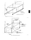
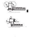
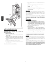
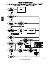
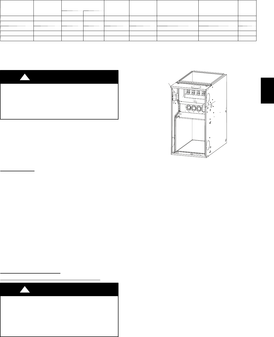
1. Remove and save two screws holding J--Box. (See Fig.
23.)
NOTE: The J--Box cover need not be removed from the J--Box
in order to move the J--Box. Do NOT remove green ground
screw inside J--Box. (See Fig. 23.)
2. Cut wire tie on loop in furnace wires attached to J--Box.
3. Move J--Box to desired location.
4. Fasten J--Box to casing with the two screws removed in
Step 1.
5. Route J--Box wires within furnace away from sharp edges,
rotating parts and hot surfaces.
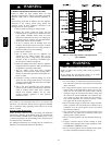
Electrical Connection to
J--Box
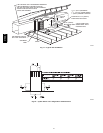
Electrical Box on Furnace Casing Side (See Fig.
24.)
FIRE OR ELECTRICAL SHOCK HAZARD
Failure to follow this warning could result in personal
injury, death, or property damage.
If field--supplied manual disconnect switch is to be mounted
on furnace casing side, select a location where a drill or
fastener cannot damage electrical or gas components.
!
WARNING
Factory
Factory
Installed
Installed
Alternate
Alternate
Location
Location
A10291
Fig. 23 -- Relocating J--Box
1. Select and remove a hole knockout in the casing where the
electrical box is to be installed.
NOTE: Check that duct on side of furnace will not interfere with
installed electrical box.
2. Remove the desired electrical box hole knockout and posi-
tion the hole in the electrical box over the hole in the fur-
nace casing.
3. Fasten the electrical box to casing by driving two field--
supplied screws from inside electrical box into casing
steel.
4. Remove and save two screws holding J--Box. (See Fig.
23.)
5. Pull furnace power wires out of 1/2--in. (12 mm) diameter
hole in J--Box. Do not loosen wires from strain--relief
wire--tie on outside of J--Box.
6. Route furnace power wires through holes in casing and
electrical box and into electrical box.
7. Pull field power wires into electrical box.
8. Remove cover from furnace J--Box.
9. Route field ground wire through holes in electrical box
and casing, and into furnace J--Box.
10. Reattach furnace J--Box to furnace casing with screws re-
movedinStep4.
11. Secure field ground wire to J--Box green ground screw.
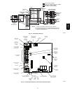
12. Complete electrical box wiring and installation. Connect
line voltage leads as shown in Fig. 24. Use best practices
(NEC in U.S. for wire bushings, strain relief, etc.
13. Reinstall cover to J--Box. Do not pinch wires between
cover and bracket.
315AAV