


47
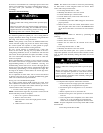
the furnace, and conditioned air is discharged upward. Since this
furnace can be installed in any of the 4 positions shown in Fig. 4,
you must revise your orientation to component location
accordingly.
Electrical Controls and W
iring
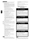
ELECTRICAL SHOCK HAZARD
Failure to follow this warning could result in personal injury
or death.
There may be more than one electrical supply to the furnace.
Check accessories and cooling unit for additional electrical
supplies that must be shut off during furnace servicing. Lock
out and tag switch with a suitable warning label.
!
WARNING
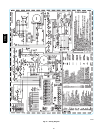
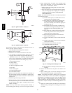
The electrical ground and polarity for 115--v wiring must be
properly maintained. Refer to Fig. 25 for field wiring information
and to Fig. 53 for furnace wiring information.
NOTE: If the polarity is not correct, the STATUS LED on the
control will flash rapidly and prevent the furnace from heating.
The control system also requires an earth ground for proper
operation of the control and flame--sensing electrode.
The 24--v circuit contains an automotive--type, 3--amp. fuse
located on the control. (See Fig. 26.) Any shorts of the 24--v
wiring during installation, service, or maintenance will cause this
fuse to blow. If fuse replacement is required, use ONLY a 3--amp.
fuse. The control LED will display status code 24 when fuse
needs to be replaced.
Proper instrumentation is required to service electrical controls.
The control in this furnace is equipped with a Status Code LED
(Light--Emitting Diode) to aid in installation, servicing, and
troubleshooting. Status codes can be viewed at the sight glass in
blower access door. The amber furnace control LED is either ON
continuously, rapid flashing, or a code composed of 2 digits. The
first digit is the number of short flashes, the second digit is the
number of long flashes.
For an explanation of status codes, refer to service label located
on blower access door or Fig. 52, and the troubleshooting guide
which can be obtained from your distributor.
See Fig. 58, a brief Troubleshooting Guide.
For 2--Stage Variable Speed ECM Controls the stored status
codes will NOT be erased from the control memory, when 115--
or 24--v power is interrupted. The control will store up to the last
7 Status Codes in order of occurrence.
1. To retrieve status codes, proceed with the following:
NOTE: NO thermostat signal may be present at control, and all
blower--OFF delays must be completed.
a. Leave 115--v power to furnace turned on.
b. Remove outer access door.
c. Look into blower access door sight glass for current
LED status.
d. Remove blower access door.
NOTE: The Status Codes cannot be retrieved by disconnecting
the limit switch or draft safeguard switch. To retrieve Status
Codes, follow the procedure below.
2. Turn Setup Switch, SW1--1 “ON.”
3. Manually close blower access door switch.
4. Control will flash up to 7 Status Codes.
5. The last Status Code, or 8th Code, will be Code 11.
6. Turn SW1--1 “OFF.”
7. A continuously--lit Amber LED will appear and indicates
proper operation.
8. Release blower access door switch, install blower access
door and replace outer door or refer to the SERVICE label
on the front of the blower access door for more informa-
tion.
Component Self--T
est
Component Test can ONLY be initiated by performing the
following:
1. Remove outer access door.
2. Remove blower access door.
3. Remove the wire from the “R” terminal of the control
board.
4. Turn Setup Switch, SW--1--6 “ON.”
5. Manually close blower access door switch.
Blower access door switch opens 115--v power to control. No
component operation can occur unless switch is closed. Caution
must be taken when manually closing this switch for service
purposes.
ELECTRICAL SHOCK HAZARD
Failure to follow this warning could result in personal injury,
or death.
Blower access door switch opens 115--v power to furnace
control. No component operation can occur unless switch is
closed. Exercise caution to avoid electrical shock from
exposed electrical components when manually closing this
switch for service purposes.
!
WARNING
6. Component Test sequence will function as follows:
a. Inducer motor starts on high--speed and continues to
run until Step (d.) of component test sequence.
b. Hot surface igniter is energized for 15 sec, then deen-
ergized.
c. Blower operates for 10 sec, then turns off.
d. Inducer motor goes to low--speed for 10 seconds, then
turns off.
e. After component test is completed, one or more status
codes (11, 25, or 41) will flash. See component test
section of service label for explanation of status codes.
NOTE: To repeat component test, turn setup switch SW1--6 OFF
then back ON.
f.TurnsetupswitchSW1--6OFF.
315AAV