


37
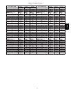
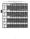
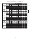
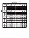
c. Find installation altitude in Table 14 or 15.
d. Find closest natural gas heat value and specific gravity
in Table 14 or 15.
e. Follow heat value and specific gravity lines to point of
intersection to find orifice size and low--and high--heat
manifold pressure settings for proper operation.
f. Check and verify burner orifice size in furnace.
NEVER ASSUME ORIFICE SIZE. ALWAYS
CHECK AND VERIFY.
NOTE: If orifice hole appears damaged or it is suspected to have
been redrilled, check orifice hole with a numbered drill bit of
correct size. Never redrill an orifice. A burr--free and squarely
aligned orifice hole is essential for proper flame characteristics.
g. Replace orifice with correct size, if required by Table
14 or 15. Use only factory--supplied orifices. See
EXAMPLE 1.
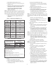
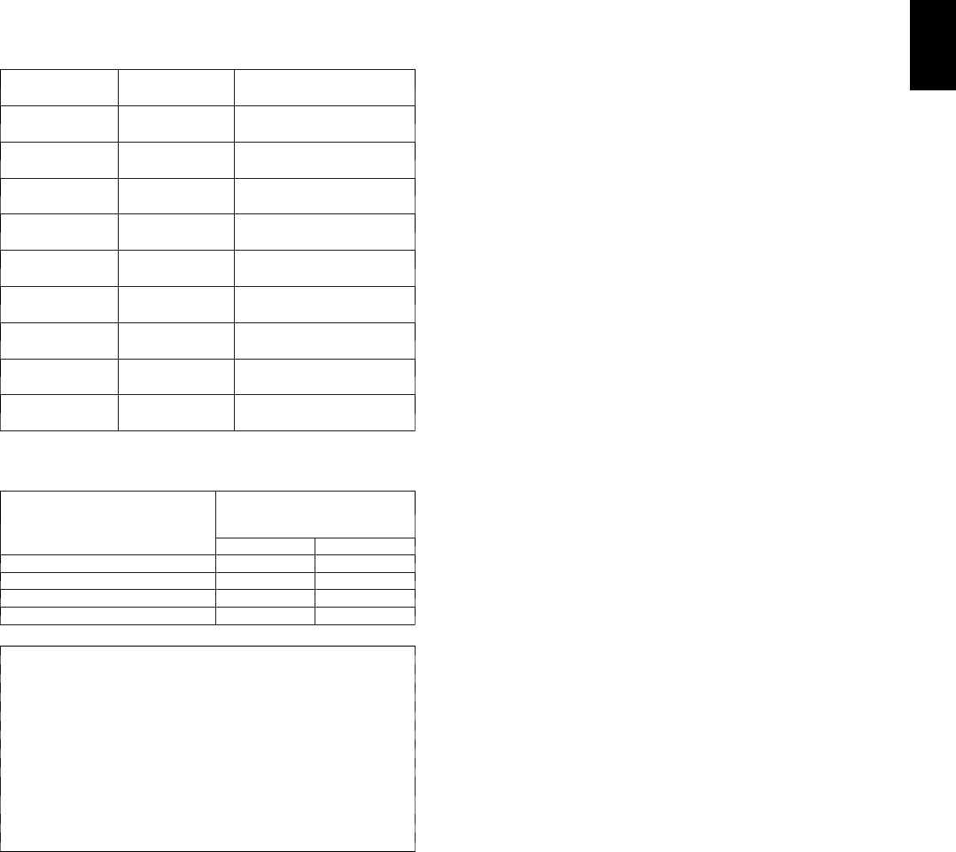
Table 11 – Altitude Derate Multiplier for U.S.A.
ALTITUDE
FT. (M)
PERCENT
OF DERATE
DERATE MULTIPLIER
FACTOR*
0–2000
(0---610)
0 1.00
2001–3000
(610---914)
8–12 0.90
3001–4000
(914---1219)
12–16 0.86
4001–5000
(1219---1524)
16–20 0.82
5001–6000
1524---1829)
20–24 0.78
6001–7000
(1829---2134)
24–28 0.74
7001–8000
(2134---2438)
28–32 0.70
8001–9000
(2438---2743)
32–36 0.66
9001–10,000
(2743---3048)
36–40 0.62
Table 12 – Blower Off Delay Setup Switch
DESIRED HEATING MODE
BLOWER OFF DELAY (SEC.)
SETUP SWITCH
(S W --- 7 A ND --- 8)
POSITION
SW1 --- 7 SW1---8
90 OFF OFF
120 ON OFF
150 OFF ON
180 ON ON
EXAMPLE 1: 0–2000 ft. (0--610 M) altitude
For 22,000 Btuh per burner application use Table 14.
Heating value = 1000 Btuh/cu ft.
Specific gravity = 0.62
Therefore: Orifice No. 43*
Manifold pressure: 3.7--In. W.C. for high--heat
1.6--In. W.C. for low--heat
* Furnace is shipped with No. 43 orifices. In this example all
main burner orifices are the correct size and do
not need to be changed to obtain proper input rate.
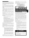
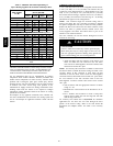
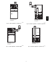
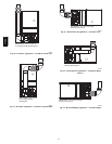
3. Adjust manifold pressure to obtain low fire input rate. (See
Fig. 49.)
a. Turn gas valve ON/OFF switch to OFF.
b. Remove manifold pressure tap plug from gas valve.
c. Connect a water column manometer or similar device
to manifold pressure tap.
d. Turn gas valve ON/OFF switch to ON.
e. Move setup SW1—2 on furnace control to ON posi-
tion to lock furnace in low--heat operation. (See Table
10 and Fig. 24.)
f. Manually close blower door switch.
g. Jumper R and W/W1 thermostat connections on con-
trol to start furnace. (See Fig. 24.)
h. Remove regulator adjustment cap from low heat gas
valve pressure regulator (See Fig. 49.) and turn low--
heat adjusting screw (3/16 or smaller flat--tipped
screwdriver) counterclockwise (out) to decrease input
rate or clockwise (in) to increase input rate.
NOTE: DO NOT set low--heat manifold pressure less than
1.4--In. W.C. or more than 1.7--In. W.C. for natural gas. If
manifold pressure is outside this range, change main burner
orifices.
i. Install low--heat regulator adjustment cap.
j. Move setup switch SW1--2 to off position after com-
pleting low--heat adjustment.
k. Leave manometer or similar device connected and
proceed to Step 4.
4. Adjust manifold pressure to obtain high fire input rate.
(See Fig. 49.)
a. Jumper R to W/W1 and W2 thermostat connections on
furnace control. This keeps furnace locked in high--
heat operation.
b. Remove regulator adjustment cap from high--heat gas
valve pressure regulator (See Fig. 49) and turn high
heat adjusting screw (3/16--in. or smaller flat--tipped
screwdriver) counterclockwise (out) to decrease input
rate or clockwise (in) to increase input rate.
NOTE: DO NOT set high--heat manifold pressure less than
3.2--In. W.C. or more than 3.8 In. W.C. for natural gas. If
manifold pressure is outside this range, change main burner
orifices to obtain manifold pressure in this range.
c. When correct input is obtained, replace caps that con-
ceal gas valve regulator adjustment screws. Main
burner flame should be clear blue, almost transparent
(See Fig. 55.)
d. Remove jumpers R to W/W1 and R to W2.
5. Verify natural gas input rate by clocking meter.
NOTE: Gas valve regulator adjustment caps must be in place for
proper input to be clocked.
a. Turn off all other gas appliances and pilots served by
the meter.
b. Move setup switch SW1--2 to ON position. This
keeps furnace locked in low--heat operation.
c. Jumper R to W/W1.
d. Run furnace for 3 minutes in low--heat operation.
e. Measure time (in sec) for gas meter to complete 1
revolution and note reading. The 2 or 5 cubic feet dial
provides a more accurate measurement of gas flow.
f. Refer to Table 13 for cubic ft. of gas per hr.
g. Multiply gas rate cu ft./hr by heating value (Btuh/cu
ft.) to obtain input. If clocked rate does not match re-
quired input from Step 1, increase manifold pressure to
increase input or decrease manifold pressure to de-
crease input. Repeat steps b through e until correct
low--heat input is achieved. Re--install low heat regu-
lator seal cap on gas valve.
h. Move setup switch SW1--2 to OFF position and jump-
er R to W/W1, and W2. This keeps furnace locked in
high--heat operation. Repeat items d through g for
high--heat operation.
315AAV