


46
Check Safety Contr
ols
The flame sensor, gas valve, and pressure switch were all checked
in the Start--up procedure section as part of normal operation.
1. Check Main Limit Switch
This control shuts off combustion system and energizes
air--circulating blower motor, if furnace overheats. By us-
ing this method to check limit control, it can be established
that limit is functioning properly and will operate if there
is a restricted return--air supply or motor failure. If limit
control does not function during this test, cause must be
determined and corrected.
a. Run furnace for at least 5 minutes.
b. Gradually block off return air with a piece of card-
board or sheet metal until the limit trips.
c. Unblock return air to permit normal circulation.
d. Burners will re--light when furnace cools down.
2. Check draft safeguard switch. The purpose of this control
is to cause the safe shutdown of the furnace during certain
blocked vent conditions.
a. Verify vent pipe is cool to the touch.
b. Disconnect power to furnace and remove vent con-
nector from furnace vent elbow.
c. Restore power to furnace and set room thermostat
above room temperature.
d. After normal start--up, allow furnace to operate for 2
minutes, then block vent elbow in furnace 80 percent
of vent area with a piece of flat sheet metal.
e. Furnace should cycle off within 2 minutes. If gas does
not shut off within 2 minutes, determine reason draft
safeguard switch did not function properly and correct
condition.
f. Remove blockage from furnace vent elbow.
g. Switch will auto--reset when it cools.
h. Re--install vent connector.
NOTE: Should switch remain open longer than 3 minutes,
furnace control board will lockout the furnace for 3 hours. To
reset furnace control board, turn thermostat below room
temperature or from HEAT to OFF and turn 115--v power OFF,
then back ON.
3. Check Pressure Switch(es)
This control proves operation of the draft inducer blower.
a. Turn off 115--v power to furnace.
b. Disconnect inducer motor lead wires from wire har-
ness.
c. Turn on 115--v power to furnace.
d. Set thermostat to “call for heat” and wait 1 minute.
When pressure switch is functioning properly, hot sur-
face igniter should NOT glow and control diagnostic
light flashes a status code 32. If hot surface igniter
glows when inducer motor is disconnected, shut down
furnace immediately.
e. Determine reason pressure switch did not function
properly and correct condition.
f. Turn off 115--v power to furnace.
g. Reconnect inducer motor wires, replace outer door,
andturnon115--vpower.
h. Blower will run for 90 seconds before beginning the
call for heat again.
i. Furnace should ignite normally.
Checklist
1. Put away tools and instruments. Clean up debris.
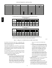
2. Verify that switches SW1--1 and SW1--6 are OFF and oth-
er setup switches are set as desired. Verify that switches
SW1--7andSW1--8fortheblowerOFFDELAYaresetas
desired per Table 10.
3. Verify that blower and burner access doors are properly in-
stalled.
4. Cycle test furnace with room thermostat.
5. Check operation of accessories per manufacturer’s instruc-
tions.
6. Review User’s Guide with owner.
7. Attach literature packet to furnace.
SERVICE AND MAINTENANCE
PROCEDURES
FIRE, INJURY OR DEATH HAZARD
Failure to follow this warning could result in personal
injury, death and/or property damage.
The ability to properly perform maintenance on this
equipment requires certain knowledge, mechanical skills,
tools, and equipment. If you do not possess these, do not
attempt to perform any maintenance on this equipment
other than those procedures recommended in the User’s
Manual.
!
WARNING
ENVIRONMENTAL HAZARD
Failure to follow this caution may result in environmental
pollution.
Remove and recycle all components or materials (i.e. oil,
refrigerant, control board, etc.) before unit final disposal.
CAUTION
!
ELECTRICAL SHOCK, FIRE OR EXPLOSION
HAZARD
Failure to follow this warning could result in personal
injury or death, or property damage.
Before installing, modifying, or servicing system, main
electrical disconnect switch must be in the OFF position and
install a lockout tag. There may be more than one
disconnect switch. Lock out and tag switch with a suitable
warning label. Verify proper operation after servicing.
!
WARNING
ELECTRICAL OPERATION HAZARD
Failure to follow this caution may result in improper
furnace operation or failure of furnace.
Label all wires prior to disconnection when servicing
controls. Wiring errors can cause improper and dangerous
operation.
CAUTION
!
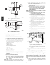
General
These instructions are written as if the furnace is installed in an
upflow application. An upflow furnace application is where the
blower is located below the combustion and controls section of
315AAV