


34
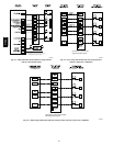
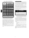
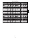
Caution!! For the following applications, use the minimum vertical heights as specified below.
For all other applications, follow exclusively the National Fuel Gas Code.
FURNACE
ORIENT ATION
VENT ORIENTATION FURNACE INPUT
(BTUH/HR)
MIN. VENT
DIAMETER
IN. (mm)*
MIN. VERTICAL VENT
HEIGHT
FT. (M)**
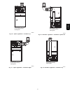
Downflow
Vent elbow left, then up
Fig. 36
154,000 132,000 110,000 5 (127) 12 (3.6)
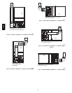
Horizontal Left
Vent elbow right, then up
Fig.
39
154,000 132,000 5 (127) 7 (2.1)
Horizontal Left
Vent Elbow up
Fig. 40
154,000 132,000 5 (127) 7 (2.1)
Horizontal Left
Vent elbow right
Fig. 41
154,000 5 (127) 7 (2.1)
Downflow
Vent elbow up then left
Fig. 34
110,000 5 (127) 10 (3.0)
Downflow
Vent elbow up, then right
Fig. 37
110,000 5 (127) 10 (3.0)
NOTE: All vent configurations must also meet National Fuel Gas Code venting requirements NFGC.
*4---in. (102 mm) inside casing or vent guard
**Including 4 in. (102 mm) vent section(s)
The horizontal portion of the venting system shall slope upwards
not less than 1/4--in. per linear ft. (21 mm/m) from the furnace to
the vent and shall be rigidly supported every 5 ft. (1.5 M) or less
with metal hangers or straps to ensure there is no movement after
installation.
Sidewall V
enting
This furnace is not approved for direct sidewall horizontal
venting.
Per section 12.4.3 of the NFPA 54/ANSI Z223.1--2009, any
listed mechanical venter may be used, when approved by the
authority having jurisdiction.
Select the listed mechanical venter to match the Btuh input of the
furnace being vented. Follow all manufacturer’s installation
requirements for venting and termination included with the listed
mechanical venter.
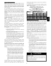
START--UP, ADJUSTMENT, AND SAFETY
CHECK
General
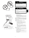
FIRE HAZARD
Failure to follow this warning could result in personal injury,
death or property damage.
This furnace is equipped with manual reset limit switches in
the gas control area. The switches open and shut off power to
the gas valve, if a flame rollout or overheating condition
occurs in the gas control area. DO NOT bypass the switches.
Correct problem before resetting the switches.
!
WARNING
1. Maintain 115--v wiring and ground. Improper polarity will
result in rapid flashing LED and no furnace operation.
2. Make thermostat wire connections at the 24--v terminal
block on the furnace control. Failure to make proper con-
nections will result in improper operation. (See Fig. 25 --
34.)
3. Gas supply pressure to the furnace must be greater than
4.5--In. W.C. (0.16 psig ) but not exceed 14--In. W.C. (0.5
psig).
4. Check all manual--reset switches for continuity.
5. Replace blower compartment door. Door must be in place
to operate furnace.
6. Setup switch descriptions The variable speed furnace con-
trol has DIP switches to select thermostat staging, blower
off delay timings, air flow selection and other operational
or service related functions. (See Fig. 26, 53 and Table
10.)
CUT HAZARD
Failure to follow this caution may result in personal injury.
Sheet metal parts may have sharp edges or burrs. Use care
and wear appropriate protective clothing, safety glasses and
gloves when handling parts, and servicing furnaces.
CAUTION
!
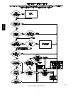
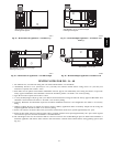
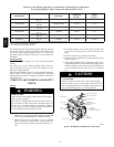
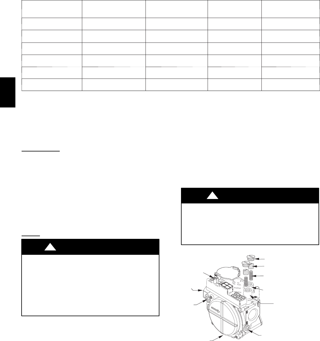
REGULATOR COVER SCREW
PLASTIC ADJUST SCREW
LOW STAGE
GAS PRESSURE
REGULATOR ADJUSTMENT
MANIFOLD
PRESSURE TAP
INLET
PRESSURE TAP
ON/OFF SWITCH
REGULATOR SPRING
HIGH STAGE GAS
PRESSURE REGULATOR
ADJUSTMENT
1/2˝ NPT OUTLET
1/2˝ NPT INLET
A04167
Fig. 49 -- Redundant Automatic Gas Control Valve
315AAV