


38
6. Set Temperature Rise
NOTE: Blower access door must be installed when taking
temperature rise reading. Leaving blower access door off will
result in incorrect temperature measurements.
FURNACE DAMAGE HAZARD
Failure to follow this caution may result in shorten furnace
life.
Set air temperature rise within limits specified on the rating
plate to prevent reduced life of furnace components.
Operation is within a few degrees of the mid--point of rise
rangewhensetupswitchSW1--4isOFF.
CAUTION
!
UNIT DAMAGE HAZARD
Failure to follow this caution may result in overheating the
heat exchangers or condensing flue gases in heat exchanger
areas not designed for condensate.
Temperature rise must be within limits specified on unit
rating plate. Operation is within a few degrees of midpoint
ofriserangewhensetupswitchSW1--4isOFF.
CAUTION
!
When setup switch SW1--4 is ON, operation will be near the high
end of the rise range for improved comfort.
Furnace must operate within ranges of temperature rise specified
on the furnace rating plate. Determine air temperature rise as
follows:
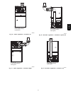
a. Place thermometers in return and supply ducts as near
furnace as possible. Be sure thermometers do not see
heat exchanger so that radiant heat does not affect
readings. This practice is particularly important with
straight--run ducts.
b. When thermometer readings stabilize, subtract return--
air temperature from supply--air temperature to determ-
ine air temperature rise.
NOTE: Temperature rise can be determined for low--heat
operation by placing setup switch SW1--2 on furnace control in
ON position. For high--heat operation, place setup switch SW1--2
in OFF position and jumper R--W2 on furnace control. DO NOT
forget to return setup switch to OFF position and remove R--W2
jumper upon completion of testing.
c. This furnace is capable of automatically providing
proper airflow to maintain the temperature rise within
the range specified on furnace rating plate. If temperat-
ure rise is outside this range, proceed as follows:
(1.) Check gas input for low-- and high--heat opera-
tion.
(2.) Check derate for altitude if applicable.
(3.) Check all return and supply ducts for excessive
restrictions causing static pressure greater than
0.5--In. W.C..
(4.) Ensure Low Heat Rise Adjust switch SW1--3 on
furnace control is in ON position when a bypass
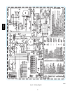
humidifier is used. (See Fig. 26 for switch loca-
tion.)
(5.) Make sure proper model plug is installed.
d. Remove thermostat jumpers and release blower access
door switch.
e. Repeat Steps a through c as required to adjust for high
heat temperature rise.
f. When correct high heat input rate and temperature rise
is achieved, turn gas valve ON/OFF switch to OFF.
g. Release blower access door switch.
h. Remove manometer or similar device from gas valve.
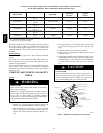
i. Re--install manifold pressure tap plug in gas valve.
(See Fig. 49.)
FIRE HAZARD
Failure to follow this warning could result in personal
injury, death, and/or property damage.
Reinstall manifold pressure tap plug in gas valve to prevent
gas leak.
!
WARNING
j. Remove thermostat jumper wire from furnace control
board.
k. Turn gas valve ON/OFF switch to ON.
FURNACE OVERHEATING HAZARD
Failure to follow this caution may result in reduced furnace
life.
Recheck temperature rise. It must be within limits specified
on the rating plate. Recommended operation is at the
mid--point of rise range or slightly above.
CAUTION
!
l. Proceed to Step 6, “Set Blower Off Delay” before in-
stalling blower access door.
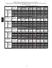
7. Set Blower Off Delay
a. Remove blower access door if installed.
b.TurnDipswitchSW--7orSW--8ONorOFFforde-
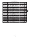
sired blower off delay. (See Table 10 and Fig. 26 and
53.)
8. Set thermostat heat anticipator.
a. Mechanical thermostat. Set thermostat heat anticipator
to match the amp. draw of the electrical components in
the R--W/W1 circuit. Accurate amp. draw readings can
be obtained at the wires normally connected to ther-
mostat subbase terminals, R and W. The thermostat
anticipator should NOT be in the circuit while measur-
ing current.
(1.) Set SW1--2 switch on furnace control board to
ON.
(2.) Remove thermostat from subbase or from wall.
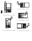
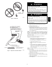
(3.) Connect an amp. meter as shown in Fig. 51.
across the R and W subbase terminals or R and
W wires at wall.
(4.) Record amp. draw across terminals when furnace
is in low heat and after blower starts.
(5.) Set heat anticipator on thermostat per thermostat
instructions and install on subbase or wall.
(6.) Turn SW1--2 switch OFF.
(7.) Install blower access door.
b. Electronic thermostat: Set cycle rate for 3 cycles per
hr.
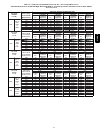
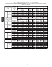
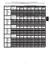
9. Set Airflow for Air Conditioning --Single Stage and High
Stage Cooling
The ECM blower can be adjusted for a range of airflow
315AAV