


51
13. Reconnect wires to the following components (Use con-
nection diagram on wiring label, if wires were not marked
for reconnection locations.):
a. Draft safeguard switch.
b. Inducer motor.
c. Pressure switches.
d. Limit overtemperature switch.
e. Gas valve.
f. Hot surface igniter.
g. Flame--sensing electrode.
h. Flame rollout switches.
14. Reinstall internal vent pipe, if applicable.
15. Reinstall vent connector on furnace vent elbow. Securely
fasten vent connector to vent elbow with 2 field--supplied,
corrosion--resistant, sheet metal screws located 180_ apart.
16. Replace blower access door only if it was removed.
17. Set thermostat above room temperature and check furnace
for proper operation.
18. Verify blower airflow and speed changes between heating
and cooling.
FIRE OR EXPLOSION HAZARD
Failure to follow this warning could result in personal
injury, death, and/or property damage.
Never purge a gas line into a combustion chamber. Never
test for gas leaks with an open flame. Use a commercially
available soap solution made specifically for the detection
of leaks to check all connections.
!
WARNING
19. Check for gas leaks.
Sequence of
Operation
NOTE: Furnace control must be grounded for proper operation
or else control will lock out. Control is grounded through
green/yellow wire routed to gas valve and burner box screw.
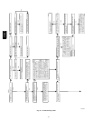
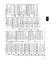
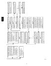
Using the schematic diagram in Fig. 53, follow the sequence of
operation through the different modes. Read and follow the
wiring diagram very carefully.
NOTE: If a power interruption occurs during a call for heat
(W/W1 or W/W1--and--W2), the control will start a 90--second
blower--only ON period two seconds after power is restored, if
the thermostat is still calling for gas heating. The amber LED
light will flash code 12 during the 90--second period, after which
the LED will be ON continuous, as long as no faults are detected.
After the 90--second period, the furnace will respond to the
thermostat normally.
The blower door must be installed for power to be conducted
through the blower door interlock switch ILK to the furnace
control CPU, transformer TRAN, inducer motor IDM, blower
motor BLWM, hot--surface igniter HSI, and gas valve GV.
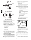
1. Two--Stage Heating (Adaptive Mode) with Single--Stage
Thermostat
See Fig. 27 -- 34 for thermostat connections
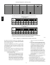
NOTE: The low--heat only switch SW1--2 selects either the
low--heat only operation mode when ON, (see item 2. below) or
the adaptive heating mode when OFF in response to a call for
heat. (See Table 10.) When the W2 thermostat terminal is
energized it will always cause high--heat operation when the
R--to--W circuit is closed, regardless of the setting of the low--heat
only switch. This furnace can operate as a two--stage furnace with
a single--stage thermostat because the furnace control CPU
includes a programmed adaptive sequence of controlled
operation, which selects low--heat or high--heat operation. This
selection is based upon the stored history of the length of
previous gas--heating periods of the single--stage thermostat.
315AAV