


5
A
A
B
[736.9]
[736.9]
29
29
Ø7/8
Ø7/8
[22.2]
[22.2]
ACCESSORY
ACCESSORY
5 15/16
5 15/16
[150.7]
[150.7]
28.39
28.39
[721.2]
[721.2]
Ø7/8
Ø7/8
[22.2]
[22.2]
ACCESSORY
ACCESSORY
14 7/8
14 7/8
[337.3]
[337.3]
(BOTH SIDES)
(BOTH SIDES)
Ø7/8
Ø7/8
[22.2]
[22.2]
ACCESSORY
ACCESSORY
Ø7/8
Ø7/8
[22.2]
[22.2]
ACCESSORY
ACCESSORY
Ø1 3/4
Ø1 3/4
[44.5]
[44.5]
GAS ENTRY
GAS ENTRY
Ø1/2
Ø1/2
[12.7]
[12.7]
THERMOSTAT WIRE ENTRY
THERMOSTAT WIRE ENTRY
22 1/16
22 1/16
[560]
[560]
SIDE INLET
SIDE INLET
(BOTH SIDES)
(BOTH SIDES)
11 7/16
11 7/16
[290.7]
[290.7]
9 11/16
9 11/16
[245.4]
[245.4]
[197.8]
[197.8]
7 13/16
7 13/16
Ø7/8
Ø7/8
[22.2]
[22.2]
J.BOX PROVISION
J.BOX PROVISION
Ø7/8
Ø7/8
[22.2]
[22.2]
JUNCTION BOX
JUNCTION BOX
LOCATION
LOCATION
Ø1 3/4
Ø1 3/4
[44.5]
[44.5]
GAS ENTRY
GAS ENTRY
1 15/16
1 15/16
[49.2]
[49.2]
1
[25.4]
[25.4]
1 1/4
1 1/4
[31.8]
[31.8]
29 9/16
29 9/16
[750.7]
[750.7]
1 15/16
1 15/16
[49.2]
[49.2]
5 5/8
5 5/8
[143.3]
[143.3]
5 7/16
5 7/16
[138.5]
[138.5]
6 13/16
6 13/16
[172.3]
[172.3]
Ø1/2
Ø1/2
[12.7]
[12.7]
THERMOSTAT WIRE ENTRY
THERMOSTAT WIRE ENTRY
19
19
[481.7]
[481.7]
OUTLET
OUTLET
D
21.6
21.6
[549.5]
[549.5]
BOTTOM INLET
BOTTOM INLET
C
33 1/4
33 1/4
[843.9]
[843.9]
9 9/16
9 9/16
[243.3]
[243.3]
3/4
3/4
[19.1]
[19.1]
5 7/8
5 7/8
[148.5]
[148.5]
3 7/16
3 7/16
[86.8]
[86.8]
9 7/8
9 7/8
[250.7]
[250.7]
27 3/4
27 3/4
[704.7]
[704.7]
2 5/16
2 5/16
[59]
[59]
FRONT OF CASING
FRONT OF CASING
TOP OF CASING
TOP OF CASING
4 13/16
4 13/16
[122.2]
[122.2]
27 3/4
27 3/4
[704.7]
[704.7]
5 7/8
5 7/8
[148.5]
[148.5]
8 5/8
8 5/8
[219]
[219]
5 1/2
5 1/2
[140.3]
[140.3]
8 7/16
8 7/16
[213.5]
[213.5]
FRONT OF CASING
FRONT OF CASING
TOP OF CASING
TOP OF CASING
6.1
6.1
[155.7]
[155.7]
2 1/16
2 1/16
[51.6]
[51.6]
5.1
5.1
[130.5]
[130.5]
1.7
1.7
[43.5]
[43.5]
Ø7/8
Ø7/8
[22.2]
[22.2]
ACCESSORY (2)
ACCESSORY (2)
AIR FLOW
AIR FLOW
AIR FLOW
AIR FLOW
BOTTOM RETURN
BOTTOM RETURN
WIDTH
WIDTH
AIR FLOW
AIR FLOW
KNOCK OUTS FOR
KNOCK OUTS FOR
VENTING(5
VENTING(5
PLACES)
PLACES)
A10290
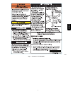
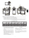
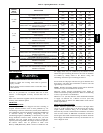
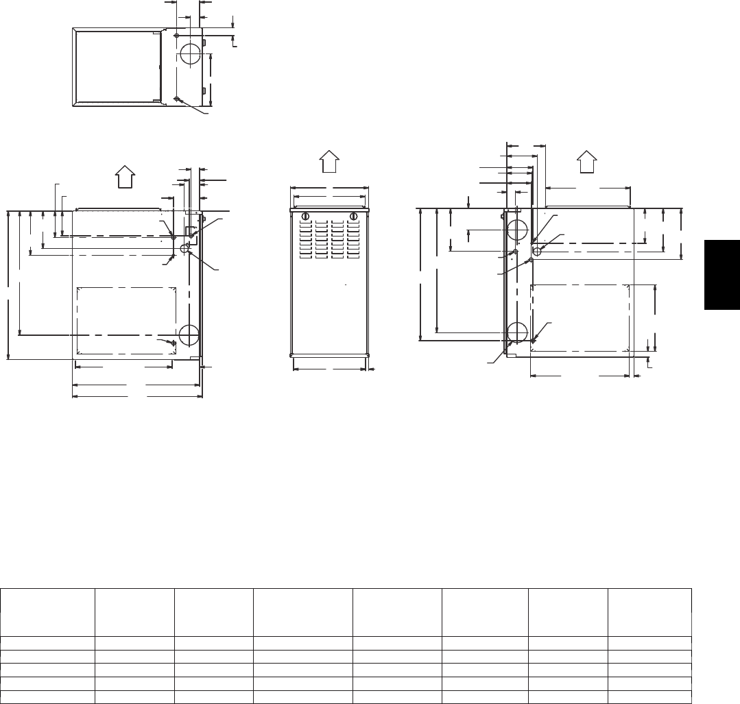
NOTES:
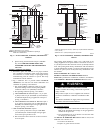
1. Two additional 7/8---in. (22 mm) diameter holes are located in t he top plate.
2. Minimum return--- air openings at furnace, based on metal duct. If flex duct is used, see flex duct manufacturer’s recommendations for equivalent diameters.
a. For 800 CFM---16---in. (406 mm) round or 14 1/2 x 12---in. (368 x 305 mm) rectangle.
b. For 1200 CFM---20---in. (508 mm) round or 14 1/2 x 19 1/2---in. (368 x 495 mm) rectangle.
c. For 1600 CFM---22---in. (559 mm) round or 14 1/2 x 22 1/16---in. (368 x 560mm) rectangle.
d. For airflow requirements above 1800 CFM, see Air Del ivery table in Product Data literature for specific use of single side inlets. The use of both sideinlets,
a combination of 1 side a nd the bottom, or the bottom only will ensure adequate retu r n air openings for airflow requirements above 1800 CFM.
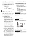
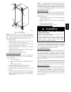
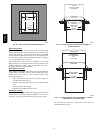
Fig. 3 -- Dimensional Drawing
Table 1 – Dimensions -- In. (mm)
FURNACE SIZE
A
CABINET
WIDTH
B
OUTLET
WIDTH
C
TOP AND
BOTTOM FLUE
COLLAR
D
BOTTOM
INLET WIDTH
VENT
CONNECTION
SIZE
SHIP WT.
LB (KG)
ACCESSORY
FIL TER MEDIA
CABINET SIZE
070---12/036070 14---3/16 (360) 12---9/16 (319) 9---5/16 (237) 12---11/16 (322) 4 (102) 115 (52) 16 (406)
090---16/048090 17---1/2 (445) 15---7/8 (403) 11---9/16 (294) 16 (406) 4 (102) 130 (59) 16 (406)
110---20/060110 21 (533) 19---3/8 (492) 13---5/16 (338) 19---1/2 (495) 4 (102) 155 (70) 20 (508)
135---22/066135 24---1/2 (622) 22---7/8 (581) 15---1/16 (383) 23 (584) 4 (102)† 166 (75) 24 (610)
155---22/066155 24---1/2 (622) 22---7/8 (581) 15---1/16 (383) 23 (584) 4 (102)† 175 (79) 24 (610)
*135 and 155 size fu rnaces require a 5 or 6---in. (127 or 152 mm) vent. Use a vent adapter between fur nace and vent stack. See Installation Instructions for
complete installation requirements.
4. If you touch ungrounded objects (and recharge your body
with static electricity), firmly touch a clean, unpainted
metal surface of the furnace again before touching control
or wires.
5. Use this procedure for installed and uninstalled (ungroun-
ded) furnaces.
6. Before removing a new control from its container, dis-
charge your body’s electrostatic charge to ground to pro-
tect the control from damage. If the control is to be in-
stalled in a furnace, follow items 1 through 4 before
bringing the control or yourself in contact with the fur-
nace. Put all used and new controls into containers before
touching ungrounded objects.
7. An ESD service kit (available from commercial sources)
mayalsobeusedtopreventESDdamage.
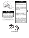
LOCATION
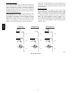
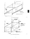
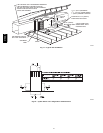
GENERAL
This multipoise furnace is shipped in packaged configuration.
Some assembly and modifications are required when used in any
of the four applications shown in Fig. 4.
NOTE: For high--altitude installations, the high--altitude
conversion kit MUST be installed at or above 5500 ft. (1676 M)
above sea level. Obtain high--altitude conversion kit from your
area authorized distributor.
315AAV