


50
A05025
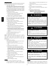
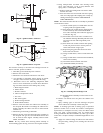
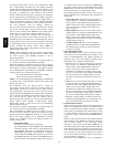
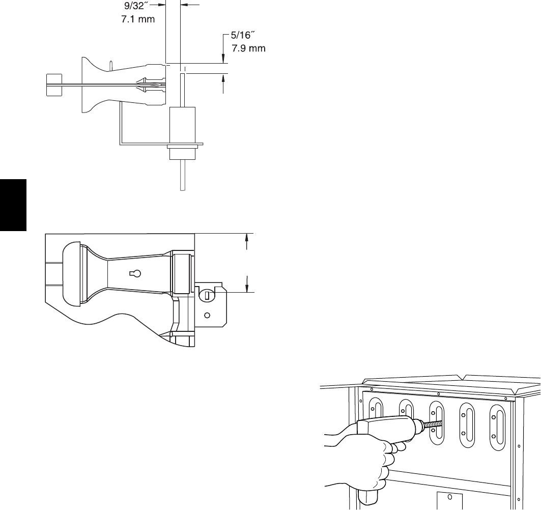
Fig. 54 -- Igniter Position -- Side View
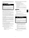
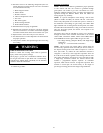
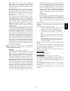
1-7/8
(47.6 mm)
A05026
Fig. 55 -- Igniter Position -- Top View
If it becomes necessary to clean the heat exchangers because of
dust or corrosion, proceed as follows:
1. Turn OFF gas and electrical power to furnace.
2. Remove outer access door.
3. Disconnect vent connector from furnace vent elbow.
4. For downflow or horizontal furnace having an internal
vent pipe, remove internal vent pipe within the casing.
5. Disconnect wires to the following components. Mark
wires to aid in reconnection (be careful when disconnect-
ing wires from switches because damage may occur):
a. Draft safeguard switch.
b. Inducer motor.
c. Pressure switches.
d. Limit overtemperature switch.
e. Gas valve.
f. Hot surface igniter.
g. Flame--sensing electrode.
h. Flame rollout switches.
6. Remove screws that fasten the collector box assembly to
the cell panel. Be careful not to damage the collector box.
Inducer assembly and elbow need not be removed from
collector box.
7. Disconnect gas line from gas manifold.
8. Remove the four screws that attach the burner assembly to
the cell panel. The gas valve and individual burners need
not be removed from support assembly. Remove NOx
baffles, if installed.
NOTE: Be very careful when removing burner assembly to
avoid breaking igniter. See Fig. 54--55 for correct igniter location.
9. Using field--provided 25--caliber rifle cleaning brush,
36--in. (914 mm) long, 1/4--in. (6 mm) diameter steel
spring cable, a variable speed, follows:
a. Remove metal screw fitting from wire brush to allow
insertion into cable.
b. Insert the twisted wire end of brush into end of spring
cable, and crimp tight with crimping tool or crimp by
striking with ball--peen hammer. TIGHTNESS IS
VERY IMPORTANT.
NOTE: The materials needed in item 9 can usually be purchased
at local hardware stores.
(1.) Attach variable--speed, reversible drill to the end
of spring cable (end opposite brush).
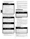
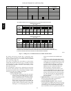
(2.) Insert brush end of cable into the outlet opening
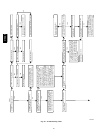
of cell and slowly rotate with drill. DO NOT
force cable. Gradually insert cable into upper pass
of cell. (See Fig. 57.)
(3.) Work cable in and out of cell 3 or 4 times to ob-
tain sufficient cleaning. DO NOT pull cable with
great force. Reverse drill and gradually work
cable out.
(4.) Insert brush end of cable in burner inlet opening
of cell, and proceed to clean 2 lower passes of
cell in same manner as upper pass.
(5.) Repeat foregoing procedures until each cell in
furnace has been cleaned.
(6.) Using vacuum cleaner, remove residue from each
cell.
(7.) Using vacuum cleaner with soft brush attachment,
clean burner assembly.
(8.) Clean flame sensor with fine steel wool.
(9.) Install NOx baffles (if removed).
A91252
Fig. 56 -- Cleaning Heat Exchanger Cell
(10.) Reinstall burner assembly. Center burners in cell
openings.
10. Remove old sealant from cell panel and collector box
flange.
11. Spray releasing agent on the heat exchanger cell panel
where collector box assembly contacts cell panel.
NOTE: A releasing agent such as cooking spray or equivalent
(must not contain corn or canola oil, aromatic or halogenated
hydrocarbons or inadequate seal may occur) and RTV sealant
(G.E. 162, 6702, or Dow--Corning 738) are needed before
starting installation. DO NOT substitute any other type of RTV
sealant. G.E. 162 (P771--9003) is available through RCD in 3--oz
tubes.
12. Apply new sealant to flange of collector box and attach to
cell panel using existing screws, making sure all screws
are secure.
315AAV