


29
Masonry Chimney Requir
ement
NOTE: These furnaces are CSA design--certified for use in
exterior tile--lined masonry chimneys with a factory accessory
Chimney Adapter Kit. Refer to the furnace rating plate for correct
kit usage. The Chimney Adapter Kits are for use with ONLY
furnaces having a Chimney Adapter Kit number marked on the
furnace rating plate.
If a clay tile--lined masonry chimney is being used and it is
exposed to the outdoors below the roof line, relining might be
required. Chimneys shall conform to the Standard for Chimneys,
Fireplaces, Vents, and Solid Fuel Burning Appliances
ANSI/NFPA 211--2009 in the United States and must be in good
condition.
U.S.A.--Refer to Sections 13.1.8 and 13.2.20 of the NFPA
54/ANSI Z223.1--2009 or the authority having jurisdiction to
determine whether relining is required. If relining is required, use
a properly sized listed metal liner, Type--B vent, or a listed
alternative venting design.
NOTE: See the NFPA 54/ANSI Z223.1--2009 13.1.9 and
13.2.20 regarding alternative venting design and the exception,
which cover installations such as our Chimney Adapter Kits
which are listed for use with these furnaces. See Table 17 for
accessory listing.
The Chimney Adapter Kit is a listed alternative venting system
for these furnaces. See the kit instructions for complete details.
This furnace is permitted to be vented into a clay tile--lined
masonry chimney that is exposed to the outdoors below the roof
line, provided:
1. Vent connector is Type--B double--wall, and
2. This furnace is common vented with at least 1 draft hood
equipped appliance, and
3. The combined appliance input rating is less than the max-
imum capacity given in Table 8, and
4. The input rating of each space heating appliance is greater
than the minimum input rating given in Table 9 for the
local 99% Winter Design Temperature. Chimneys having
internal areas greater than 38 sq. in. (24516 sq. mm) re-
quire furnace input ratings greater than the input ratings of
these furnaces. See footnote at bottom of Table 9, and
5. The authority having jurisdiction approves.
If all of these conditions cannot be met, an alternative venting
design shall be used, such as the listed chimney adapter kit with a
furnace listed for use with the kit, a listed chimney--lining system,
or a Type--B common vent.
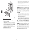
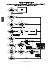
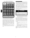
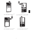
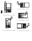
Inspections before the sale and at the time of installation will
determine the acceptability of the chimney or the need for repair
and/or (re)lining. Refer to the Fig. 33 to perform a chimney
inspection. If the inspection of a previously used tile--lined
chimney:
a. Shows signs of vent gas condensation, the chimney
should be relined in accordance with local codes and
the authority having jurisdiction. The chimney should
be relined with a listed metal liner, Type--B vent, or a
listed chimney adapter kit shall be used to reduce con-
densation. If a condensate drain is required by local
code, refer to the NFPA 54/ANSI Z223.1--2009, Sec-
tion 12.10 for additional information on condensate
drains.
b. Indicates the chimney exceeds the maximum permiss-
ible size in the tables, the chimney should be rebuilt or
relined to conform to the requirements of the equip-
ment being installed and the authority having jurisdic-
tion.
A chimney without a clay tile liner, which is otherwise in good
condition, shall be rebuilt to conform to ANSI/NFPA 211 or be
lined with a UL listed metal liner or UL listed Type--B vent.
Relining with a listed metal liner or Type--B vent is considered to
be a vent--in--a--chase.
If a metal liner or Type--B vent is used to line a chimney, no other
appliance shall be vented into the annular space between the
chimney and the metal liner.
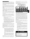
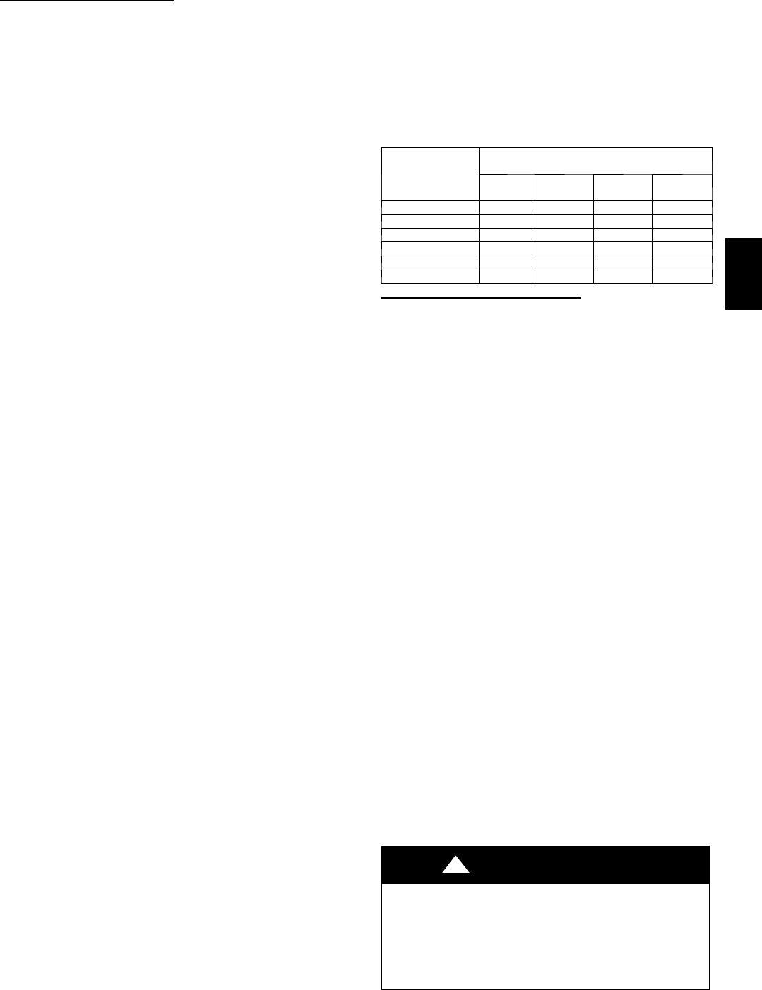
Exterior Masonry Chimney FAN + NAT
Installations with Type--B Double--Wall Vent
Connectors ENFPA & AGA
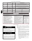
Table 8 – Combined Appliance Maximum Input
Rating in Thousands of Btuh per Hour
VENT HEIGHT
FT (M)
INTERNAL AREA OF CHIMNEY
SQ. IN. (SQ. MM)
12
(7741)
19
(12258)
28
(18064)
38
(24516)
6 (1.8) 74 119 178 257
8 (2.4) 80 130 193 279
10 (3.0) 84 138 207 299
15 (4.5) NR 152 233 334
20 (6.0) NR NR 250 368
30 (9.1) NR NR NR 404
Appliance Application Requirements
Appliance operation has a significant impact on the performance
of the venting system. If the appliances are sized, installed,
adjusted, and operated properly, the venting system and/or the
appliances should not suffer from condensation and corrosion.
The venting system and all appliances shall be installed in
accordance with applicable listings, standards, and codes.
The furnace should be sized to provide 100 percent of the design
heating load requirement plus any margin that occurs because of
furnace model size capacity increments. Heating load estimates
can be made using approved methods available from Air
Conditioning Contractors of America (Manual J); American
Society of Heating, Refrigerating, and Air--Conditioning
Engineers; or other approved engineering methods. Excessive
oversizing of the furnace could cause the furnace and/or vent to
fail prematurely.
When a metal vent or metal liner is used, the vent must be in
good condition and be installed in accordance with the vent
manufacturer’s instructions.
To prevent condensation in the furnace and vent system, the
following precautions must be observed:
1. The return--air temperature must be at least 60_F db except
for brief periods of time during warm--up from setback at
no lower than 55_F(13_C) db or during initial start--up
from a standby condition.
2. Adjust the gas input rate per the installation instructions.
Low gas input rate causes low vent gas temperatures, caus-
ing condensation and corrosion in the furnace and/or vent-
ing system. Derating is permitted only for altitudes above
2000 Ft. (610 M).
3. Adjust the air temperature rise to the midpoint of the rise
range or slightly above. Low air temperature rise can cause
low vent gas temperature and potential for condensation
problems.
4. Set the thermostat heat anticipator or cycle rate to reduce
short cycling.
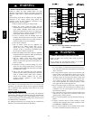
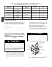
BURN HAZARD
Failure to follow this caution may result in personal injury.
Hot vent pipe is within reach of small children when
installed in downflow position.
See the following instruction.
CAUTION
!
315AAV